Vehicle fuel system – design, function, diagnostics and repair

Key facts at a glance

  • The fuel supply system as a complete system:
    The fuel system stores, filters and delivers the fuel and, depending on the injection system, supplies it at the pressure required for controlled injection.
  • Low and high-pressure systems working together:
    In direct-injection petrol engines and common-rail diesel engines, the electric fuel pump supplies the low-pressure circuit, whilst a high-pressure pump generates the required injection pressure.
  • Faults can affect the entire functional chain:
    Issues starting the engine, drop in performance or pressure fluctuations may be caused by pumps, filters, pipes, pressure control, sensors or injectors, and must be systematically pinpointed.
  • An error code does not automatically indicate a component fault:
    If the fuel pressure is too low, initially check the supply pressure and delivery quantity on the low-pressure side before assessing the high-pressure pump, pressure control and sensors.
  • Targeted combination of diagnostics methods:
    Combine fault memory, real-time data, actuator tests and electrical measurements with pressure and functional tests to narrow down fault causes and avoid unnecessary component replacements.

Important safety information

The following technical information and practical tips have been compiled by HELLA in order to provide professional support to vehicle workshops in their day-to-day work. The information provided on this website is intended for use by suitably qualified personnel only.

1. Basics

Fundamentals and system overview

The fuel system makes sure that the internal combustion engine is supplied with the required fuel quantity. For this purpose, fuel is stored in the tank, filtered, supplied to the engine and, depending on the respective injection system, supplied at the required pressure. The engine control unit regulates subsequent fuel injection in line with the current operating conditions.

Contemporary fuel systems are made up of mechanical, hydraulic and electronic components. Electronically controlled fuel pumps, fuel pressure sensors, fuel level sensors and high-pressure systems have been integrated into vehicle diagnostics. As a result, anomalies can frequently be identified using the fault memory or engine control unit readings.

Fuel system design

As a rule, the fuel system can be divided into fuel delivery and mixture formation sections. Fuel delivery starts at the fuel tank. An electric fuel pump delivers fuel to the engine through filters and pipes . In direct-injection petrol engines and common-rail diesel engines, this low-pressure circuit is linked to a high-pressure system.

Fuel supply system objectives:

  • Safely storing fuel and pumping it as required
  • Filtering out impurities
  • Consistent fuel supply to the fuel pump
  • Recording the fuel tank level

Mixture formation involves generating pressure, metering and injecting fuel as required. For this purpose, the engine control unit calculates the injection timing and injection quantity on the basis of various sensor readings.

Mixture formation objectives:

  • Generating the required fuel pressure
  • Storing and distributing fuel within the rail
  • Specifying the injection quantity and injection timing
  • Pressure control and monitoring using sensors and control units
2. Fuel supply

Fuel supply

The fuel supply system comprises, in particular, the fuel tank, fuel supply unit, the electric fuel pump, surge tank, fuel lines, fuel filter and fuel level sensor.

Fuel tank

The fuel tank is used to safely store fuel. Contemporary fuel tanks are predominantly made of multi-layered plastics and are designed to fit the available installation space within the vehicle.

As well as serving as a storage tank, the tank frequently houses other components. These include the fuel supply unit, fuel level sensor, surge tank and tank ventilation components.

Vehicles with complex fuel tank geometries may feature several fuel tank compartments. The fuel must then be transported from the various areas to the actual supply unit.

Fuel supply unit (module)

In many vehicles, several components are combined to form a fuel supply unit or a fuel module. The unit is installed in the tank and, depending on the model, may include the following components:

  • Electric fuel pump
  • Pre-filter screen
  • Swirl pot
  • Pressure control
  • Nonreturn valve
  • Fuel level sensors and electrical as well as hydraulic connections

Depending on the design, a fault in individual, integrated components may make it necessary to replace the entire supply unit.

Electric fuel pump

The electric fuel pump delivers fuel from the tank to the engine. Depending on the system, fuel pumps may be installed either inside or outside the fuel tank. In contemporary systems, they are frequently triggered on an as-needed basis by the engine control unit or a separate fuel pump control unit.

Depending on the system, the pump speed may, for example, be controlled by a pulse-width-modulated signal. This makes sure that only the required amount of fuel is supplied.

Typical low-pressure values for intake manifold injection systems range from approximately 3 to 6 bar. In direct-injection and common-rail systems, the electric pump acts as a pre-supply pump. The actually required setpoints must always be obtained from vehicle-specific manufacturer's information.

Mechanical fuel pump

Older petrol and diesel engines feature mechanical fuel pumps.

They are usually driven directly by the engine using a camshaft or an eccentric shaft.

As a result of mechanical lever and diaphragm movement, fuel is drawn in and delivered to the carburettor or fuel injection system at a specified pressure. In this process, the pump pressure is approximately 0.2 to 0.3 bar.

Swirl pot

The swirl pot, also known as a surge tank, forms a small fuel reservoir within the tank. It makes sure that the fuel pump is reliably supplied with fuel even when the fuel level is low, as well as when cornering, accelerating or braking.

The pump may draw in air if the surge tank is not filled to the required level. Potential consequences include fluctuations in pressure, stuttering engines or starting issues.

Fuel lines

Fuel lines connect the fuel tank, filters, pumps and fuel injection system. Plastic, metal or flexible pipes are used depending on the installation location and system pressure.

As part of the diagnostics procedure, check pipes and connections for leaks, kinks, chafing, corrosion and damage. Exclusively work on high-pressure pipes in accordance with vehicle manufacturer's instructions.

Fuel filter

The fuel filter cleans the fuel before it enters the combustion chamber, thereby protecting the pumps and injection components from particles and contaminants. In diesel systems, the filter often also serves as a water separator.

A blocked filter may reduce the delivery quantity. Typical effects include a drop in output, starting issues or insufficient fuel pressure.

Fuel level sensor (level sensor)

The fuel level sensor measures the fuel level in the tank. A float is used in many cases, the movement of which is transmitted to a resistance transducer or a non-contact sensor element.

Two or more transmitters may be fitted to semitrailer tanks. The individual readings are then processed by the relevant control unit to generate an overall fill level.

Common faults include worn contact tracks, damaged float mechanisms, line breaks or corroded plug connections. Potential consequences include a fluctuating fuel gauge, consistently incorrect fuel level readings or an implausible calculation of the remaining range.

3. Mixture formation

Mixture formation

Mixture formation refers to the process of preparing the fuel for optimum combustion inside the engine. In this process, the fuel is metered, mixed with air and fed into the engine in the correct quantity and at the correct time

Petrol engine – intake manifold and direct injection

Fuel is injected into the intake manifold upstream of the intake valve as part of intake manifold injection. The required fuel pressure is generated by the electric fuel supply.

With direct petrol injection, fuel is directly injected into the combustion chamber. A mechanically driven, high-pressure pump is required in addition to the low-pressure system. Depending on engine design and operating conditions, contemporary systems operate at pressures of several hundred bar.

Diesel engine – common rail

In the common-rail system, a high-pressure pump generates the required fuel pressure. The fuel is supplied to a common pressure accumulator, the rail, and distributed from there to the injectors.

Contemporary diesel systems can operate at system pressures of well over 2,000 bar. As a result of these high pressures, specific safety requirements apply to diagnosis and repair.

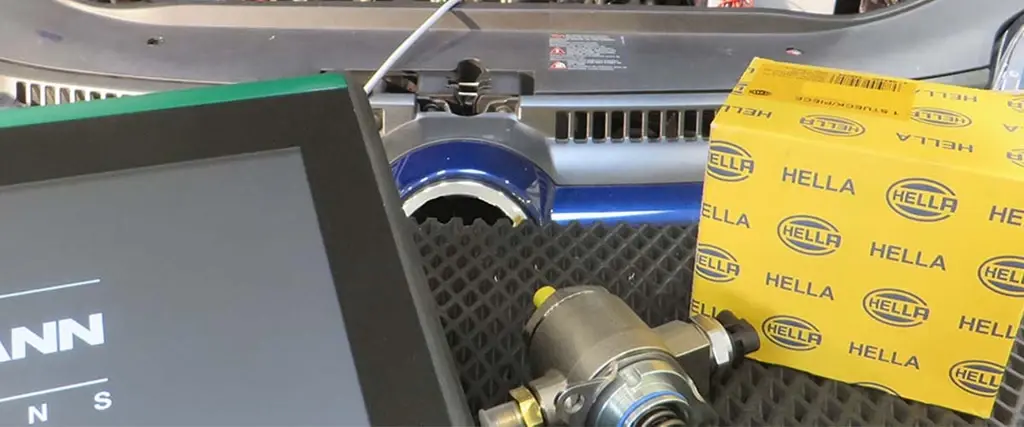
High-pressure pumps and injectors

The high-pressure pump generates the pressure required for direct injection. The injectors then meter the correct amount of fuel for each individual cylinder.

Multiple injections enable elements including pre-injection, main injection and post-injection. This makes it possible to specifically influence the combustion process, developing noise and emissions.

Sensors and engine control unit

The engine control unit regulates fuel pressure and injection based on data from various sensors. These include factors, such as fuel pressure, air mass or intake manifold pressure, crankshaft and camshaft position, engine temperature and lambda sensor values.

Unreliable input signals can affect fuel control, even though the pump or injectors are technically in perfect working order. Checking the sensor readings therefore forms part of systematic diagnostics.

Fuel types and requirements

The various fuel system components must be designed to suit the specific fuel. This applies in particular to seals, pumps, filters, pipes and injection components. Petrol and diesel differ in terms of their ignition properties, lubricity and evaporation properties, as well as their chemical properties in relation to elastomers. Additives, such as ethanol or biogenic fuel components also influence the requirements on materials used.

For this reason, exclusively fuels approved by the vehicle manufacturer for the vehicle in question must be used. Incorrect refuelling or using unauthorised fuels may damage pumps, injectors and other fuel injection system components.

4. Diagnostics, maintenance and repairs

Diagnostics, maintenance and repairs

How component failure affects the fuel system

Fuel system components form a coherent functional chain. As a consequence, a fault does not necessarily originate where the fault pattern becomes apparent. For example, if the rail pressure is too low, this may be caused by the high-pressure pump, but it may also result from an insufficient fuel supply on the low-pressure side.

AssemblyConsequences in the event of a failure or malfunctionPotential symptoms
Fuel pumpThe delivery pressure and delivery quantity decrease or cease entirely. The high-pressure pump may no longer be supplied with a sufficient amount of fuel.Starting issues, engine fails to start, drop in performance, engine stalls
Fuel pump controlPump is either not actuated, permanently actuated or actuated with an incorrect output.No engine start, sporadic stalling, pressure fluctuations
Fuel filterIncreased flow resistance reduces the fuel supply. The fault often initially becomes apparent when the engine is running at heavy load.Drop in output, difficulty starting the engine, fuel pressure too low
Swirl pot/internal tank supplyThe fuel pump may be drawing in air, particularly when the fuel level is low.Misfires when cornering, accelerating or braking
Fuel linesLeaks, restrictions in lines or an ingress of air affect pressure and delivery quantity.Drop in pressure, starting problems, smell of fuel, drop in output
Fuel level sensorThe actual fuel delivery may continue to operated correctly, but the fuel level in the tank is recorded incorrectly.Incorrect fuel gauge reading, implausible remaining range
High-pressure pumpThe system pressure required for direct injection is not being generated or it is insufficient.Starting problems, limp home mode, drop in output, engine failing to start
Fuel pressure sensorThe engine control unit is being provided with an incorrect pressure reading or no reading at all. This may affect pressure control.Engine warning light, limp home mode, starting or output problems
Pressure control valveTarget and actual fuel pressures differ.Fluctuations in pressure, engine not running smoothly, starting problems, drop in output
InjectorA cylinder's injection quantity or injection profile deviate from the target value. An injector with an internal leak may additionally affect the system pressure.Engine not running smoothly, starting problems, drop in output, increased emissions
Engine control unit/signal supplyActuation or monitoring of individual components is faulty.A range of fault patterns up to and including a complete failure of the fuel injection system

Control unit diagnostics using a diagnostic unit

The fuel system is monitored by the relevant control unit. Any faults are stored in the engine control unit's fault memory and can be read out using a suitable diagnostic unit. Cuts in the electrical supply, pressure deviations or implausible sensor signals can therefore be recorded as fault codes.

Depending on the vehicle, additional diagnostic functions, such as displaying parameters or running actuator tests, may be available. The information obtained from the control unit communication forms the fundamental basis for systematic fault diagnostics and a successful repair.

Fault memory and real-time data

The fault memory provides an initial indication of the affected area within the system. However, a fault code does not necessarily mean that a component is faulty.

The chain of events is crucial for diagnostics. If, for example, the recorded fault code is 'Fuel pressure too low', do not replace the high-pressure pump straight away. In a first step, check whether the specified supply pressure and the required delivery quantity are available on the low-pressure side. Subsequently, compare setpoint and actual values of the high-pressure system and test the pressure control and sensor systems.

Consequently, the cause of the fault and the fault memory entry do not necessarily relate to the same assembly. Fault memory, real-time data and actuator tests must always be analysed in conjunction with electrical and hydraulic tests. This makes it possible to systematically narrow down the chain of faults from the fuel tank to the injector.

Actuator tests

Actuator diagnostics can, for example, be used to actuate the electric fuel pump in a targeted manner. This allows you to check whether the pump is responding and whether the pressure is building up as it should.

Depending on the system, pressure control valves or other actuators may also be actuated. If there is no response, check the power supply, ground connection, wiring and actuation before replacing any component.

5. Conclusion

Conclusion

The fuel system in contemporary vehicles combines fuel storage, controlled delivery and precise injection technology to form a complex, integrated system. For workshops, the interaction between the electric fuel pump, delivery unit, level sensor, pressure control and engine control unit is particularly important.

Successful troubleshooting is therefore not based solely on mechanical tests. Fault memory, real-time data, actuator tests and electrical measurements must be combined with pressure and functional tests. This makes it possible to pinpoint the causes of faults and avoid unnecessary component replacements.

Important! 

The information, technical specifications and test procedures set out here are exclusively provided for general technical information purposes and are not a substitute for vehicle-specific repair information. System configuration, operating pressures, diagnostic functions and repair procedures may vary depending on the vehicle manufacturer, model, engine type and year of manufacture.

Always observe vehicle-specific guidelines, safety information and applicable legal requirements during diagnostics, maintenance and repair work. Exclusively work on fuel and high-pressure systems using suitable workshop equipment and after having appropriately qualified.

6. FAQs

FAQs – mixture formation

Why must the low-pressure side be tested first if the rail pressure is too low?

This is because insufficient pre-supply may result in the high-pressure pump not being provided with enough fuel and therefore being unable to build up the required rail pressure. An in-depth assessment of the high-pressure system only makes sense once the supply pressure is correct and the delivery quantity is sufficient.

Why is a fault code indicating low fuel pressure not a clear indication of a faulty high-pressure pump?

Because pressure fluctuations can also be caused by a blocked fuel filter, an insufficiently operating pre-supply pump, pipe issues, faulty pressure control, malfunctioning sensors or injectors with internal leaks. Consequently, always test the entire system.

Why might the fuel pressure appear normal at idle, even though there is a lack of output under load?

As fuel consumption significantly increases under load, a restricted flow rate, for instance caused by a clogged filter or worn-out pump, only leads to a relevant deviation between pressure setpoint and actual pressure value at an increased volume flow.

How significant is the vehicle electrical system voltage in diagnosing an electric fuel pump?

An excessively low supply voltage or increased contact resistance may reduce the pump speed and flow rate, even though the fuel pump is mechanically intact. Therefore, test the power supply, ground connection and control system under real operating conditions.

Why can engine misfires at a low fuel level indicate problems with the internal fuel supply system?

The fuel pump may briefly draw in air whilst cornering, accelerating or braking if the surge tank is not filled to the required level, causing the delivery pressure and delivery quantity to significantly drop and potentially result in sporadic misfires.

Why is a successful actuator test on the fuel pump not sufficient proof of a correctly operating system?

An actuator test initially merely confirms that pump control is operational and generally responding. Assess whether it achieves the specified pressure and the required flow rate in the relevant operating conditions on the basis of additional measured values and functional tests.

Why can implausible sensor data appear to be a mechanical fault in the fuel system?

The engine control unit uses sensor values as control variables for fuel pressure and injection and consequently, faulty input signals may lead to incorrect management of pumps, control valves or injectors, even though the relevant actuators are technically intact.

Why is it particularly important to check for contaminants and safeguard correct bleeding after having worked on the fuel filter?

Particles or trapped air in the fuel system may impair pressure control, put a strain on sensitive high-pressure components and lead to starting problems or pressure fluctuations immediately after repair; a clean working environment is therefore crucial, particularly for common rail systems.

How helpful is this article for you?

Not helpful at all
5
4
3
2
1
Very helpful
Success

Wrong Captcha

Wrong Captcha

Error

Something went wrong

Spare Parts Finder
Manual vehicle identification OE-No.
Top manufacturers
Other manufacturers
Vehicle series Back
Vehicle Back

Enter the OE number in the input field. You will usually find the OE number on the spare part itself or in the vehicle documents.

Spare Parts Finder
Also determine spare parts with OE numbers Detailed product information Find wholesalers near you
dummy
Processing Selected Car
Manufacturer
Vehicle series
Vehicle
Engine output
Engine displacement
Fuel type
Construction year
Engine code

Choose category:
Back
dummy
Teilen Sie
Send via Copy link
URL copied to the clickboard !
Article NUmber
Number
Article Number Was Copied !
Search The Web Mounting Instructions
More Details
Name Value
Less Details

Your Dealer
Autoteile Krammer GmbH
dummy
Lechstraße 1-3
68199 Mannheim
Show Map

Further technical information

Injection nozzle/injection valve
Basic Knowledge
Injection nozzle/injection valve – Function & checks
Find out how to diagnose a defective fuel injector and replace it in the workshop.
Reading Time: 6 minutes
Checking a high-pressure fuel pump
Basic Knowledge
Checking a high-pressure fuel pump
An overview of the structure and function of the high-pressure fuel pump - with information on fault diagnosis.
Reading Time: 8 minutes
IBS sensor
Basic Knowledge
IBS sensor: Function, faults and diagnostics
This article explains how the IBS sensor works in energy management and how to systematically diagnose typical faults.
Reading Time: 12 minutes
Central locking system
Basic Knowledge
Central locking system: function and troubleshooting
How does a central locking system work and what causes typical faults? Find out which components work together and how to identify electrical and mechanical faults­.
Reading Time: 8 minutes
A vehicle with an active ADAS system recognises pedestrians and e-scooters in urban traffic by means of radar and sensor signals – a good example of autonomous driving and sensor fusion.
Basic Knowledge
ADAS and autonomous driving: an overview for workshops
Everything you need to know about ADAS and autonomous driving: functions, sensor fusion, AI and diagnostic devices – concisely explained for automotive professionals
Reading Time: 14 minutes
E-mobility
Basic Knowledge
E-mobility in everyday workshop activities: technology and requirements
Electromobility is changing workshop processes: find out how workshops handle high-voltage systems, new diagnostics procedures and targeted qualifications
Reading Time: 16 minutes
Tire pressure monitoring system tpms
Basic Knowledge
TPMS – tyre pressure monitoring system
Overview of direct and indirect tire pressure monitoring systems (TPMS) - everything you need to know for the vehicle workshop.
Reading Time: 15 minutes
Electric hatchback actuator
Basic Knowledge
Electric hatchback actuator: troubleshooting
Find out how to systematically diagnose and specifically narrow down common faults in the electric hatchback actuator.
Reading Time: 8 minutes
HELLA 77 GHz radar sensors: Design, function and applications
Basic Knowledge
Maintenance and diagnostics of 77 GHz radar sensors
Find out how the HELLA 77 GHz radar sensor supports driver assistance systems and accurately identifies objects in any weather conditions. Discover the design, function and applications in the vehicle.
Reading Time: 7 minutes
Basic Knowledge
Checking the exhaust gas temperature sensor
Step-by-step instructions for testing the exhaust gas temperature sensor - shown on the VW Passat 2.0 TDI.
Reading Time: 3 minutes

This might also interest you

Quick question

How likely is it that you would recommend HELLA?

highly unlikely
very likely
highly unlikely
very likely

Thank you very much!

Your feedback helps us to further develop our services.