Spare Parts Finder
Manual vehicle identification
OE-No.
Top manufacturers
Other manufacturers


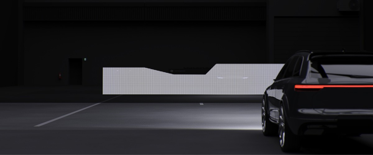
Today LED headlamps are now standard equipment in many Asian vehicle models. Hyundai and Toyota vehicles, in particular, use LED lighting systems for low beam, high beam, daytime running lights and also for adaptive light functions. Compared with halogen or xenon systems, LED lamps offer high luminous efficacy whilst consuming little power and boasting a compact design.
At the same time, however, the demands placed on diagnostics, calibration and repairs are increasing.
During the day-to-day workshop routine, in addition to electrical tests, knowledge of control unit communication, temperature management and driver assistance systems is becoming increasingly necessary. Modern LED headlamps are often linked to cameras, radar or control unit systems and form part of ADAS functions. The following information is presented using a Toyota LED headlamp as an example.
Key features at a glance: “ LED lamps of the Asian Range”
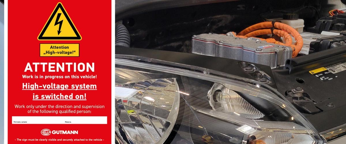
Important safety information
The following technical information and practical tips have been compiled by HELLA in order to provide professional support to vehicle workshops in their day-to-day work. The information provided on this website is intended for use by suitably qualified personnel only.
LED headlamps consist of several electronic and optical components that work in coordination with one another. Unlike conventional halogen lamps, the light is generated not by a filament but by semiconductor component parts.
The key components of an LED headlamp are LED modules for low beam and high beam, electronic control units, heat sinks, projection or reflector systems, daytime running light and direction indicator modules, headlamp levelling, and also the sealed housing.
The hybrid headlamp shown below combines LED and halogen technology to provide a range of light functions.
The low beam, high beam and daytime running light functions are produced by LED components. The direction indicator is powered by a halogen bulb.
The most common causes of faults include moisture in the lamp housing, faulty LED driver control units, and also interruptions or short circuits in the power supply. Other relevant factors include external damage or mechanical faults, damaged plug connections, thermal overloads in the LED modules and communication errors in the vehicle electrical system.
Possible symptoms include flickering LED segments, the failure of individual light functions, error messages on the instrument cluster or faulty adaptive light distribution.
A systematic approach is required when diagnosing faults in LED headlamps. In addition to the lamp itself, the electrical peripherals and the control system linked to the vehicle’s electrical system are also to be checked for possible faults.
At the start of the diagnostic process, the customer’s complaint should be recorded in detail. Here it is important to establish which light function is affected (e.g. low beam, high beam, daytime running lights or direction indicators), whether the fault occurs continuously or intermittently, and whether one or both sides of the vehicle are affected. This information helps to narrow down the scope of further troubleshooting.
After replacing a control unit or an LED lamp, it may be necessary that vehicle-specific adjustments have to be carried out.
Depending on the vehicle model, the lamp design and also the control unit that has been fitted, additional work using a suitable diagnostic device is required in order to ensure that the lighting system is functioning correctly.
In the repair instructions issued by the vehicle manufacturer Toyota, these procedures are often referred to as adjustment, calibration, initialisation or registration. Such measures serve to ensure that new or replaced components are correctly integrated in the vehicle and that they function properly.
In this context the terms can be described as follows:
Registration
During registration, a new control unit or component is identified in the vehicle. This enables the vehicle to recognise the fitted component and match it to the existing system functions and vehicle data.
Initialisation
Initialisation is the first setup of a new or replaced component. This involves creating basic operating data and integrating the control unit or component into the vehicle system.
Setting
During setting, existing parameters or functions are adjusted to suit the vehicle’s specifications. This includes, for example, setting the luminous range or adjusting certain system values following a repair.
Calibration
During calibration, the system determines reference values and matches sensors or actuators to defined set values. This ensures that functions such as automatic headlamp levelling and LED lighting systems operate precisely.
Calibration may be required following the removal or replacement of a headlamp, after accident repairs, following work on the chassis or after changes have been made to the vehicle’s height.
So as to guarantee correct calibration, the vehicle must be parked on a level surface. Tyre pressure, vehicle level and vehicle electrical system voltage must be checked before any work begins. In addition, all the manufacturer’s specifications are to be strictly observed.
Repair information
Work on LED headlamps requires careful handling of electronic components. A stable power supply, suitable diagnostic equipment and ESD protective measures are essential for carrying out repairs to a professional standard.
In the case of vehicles fitted with driver assistance systems, additional system tests and calibrations often have to be carried out following repairs.
Depending on the vehicle model and lamp type, control units, fans, headlamp levelling motors or brackets can be replaced separately. Faulty LED modules or damaged circuit boards, on the other hand, often mean that the entire lamp unit has to be replaced.
Modern LED headlamps in Asian vehicles combine lighting technology, electronics and driver assistance systems to form highly integrated, complete systems.
The Toyota RAV4 illustrates the increasing integration of modern LED headlamps into the vehicle architecture. The light functions are coordinated via various control units and are closely linked to the driver assistance systems.
For the workshop, this means that increasing demands are placed on the staff as regards diagnostics, calibration and repairs. Systematic troubleshooting, compliance with the manufacturer’s specifications and also the use of appropriate diagnostic and calibration equipment form the basis for safe and professional repairs.
Important!
The information, illustrations and examples of work processes presented in this article are intended solely to explain technical concepts and to promote a general understanding of modern vehicle lighting. They are not a substitute for vehicle-specific repair, testing or adjustment instructions.
Work on lighting systems, driver assistance systems and their associated sensors and control units is to be carried out exclusively in accordance with the relevant vehicle manufacturer’s specifications and only with suitable diagnostic and calibration equipment. Throughout such work, the applicable legal provisions and also the relevant manufacturer’s instructions are to be strictly observed.
Vehicle equipment, system functions and diagnostic procedures may vary depending on the manufacturer, model, year of manufacture and software version. The vehicle manufacturer’s current repair and service information is therefore always the authoritative source.
Further information on the subject of LED lamps can be found on the pages dealing with the following topics:
Adjusting and replacing LED lamps | HELLA
CSC-Tool PRO – fully digital ADAS calibration | Hella Gutmann
The light source is just one component of the complete system. Faults in control units, bus communication or the sensor system may result in individual light functions being deactivated or restricted. For this reason, the diagnosis should always take into account not only the electrical tests but also communication with the relevant control units and also the stored diagnostic parameters. A fully functional LED module does not rule out the possibility of a system fault.
The light output and service life of LEDs depend largely on their operating temperature. Heat sinks, fans or heat-conductive components ensure that the permissible barrier layer or junction temperatures are not exceeded. Dirt, damaged fans or restricted heat dissipation can lead to reduced performance, premature wear or to the failure of individual LED modules. That is why checking the cooling system forms part of a systematic diagnosis.
Work carried out on the chassis, axle geometry or vehicle height alters the vehicle’s spatial position. As a result, the reference values for the automatic headlamp levelling system and other light functions may no longer correspond to the actual vehicle data. Calibration ensures that sensors and actuators are once again operating at the correct setpoints and that the light distribution complies with the manufacturer’s specifications.
LED headlamps form part of a networked vehicle system. The control units continuously exchange information with the vehicle electrical system and also with other systems, such as the camera, steering and driving dynamics control units. Faults on the CAN or LIN bus can therefore affect light functions, even though there is no fault with the lamp itself. A bus diagnostic check is therefore an essential part of thorough troubleshooting.
New components do not initially have the vehicle-specific parameters for the vehicle in question. It is only through registration, initialisation or parameter setting that they are correctly integrated into the vehicle architecture. Depending on the system, identification data, configuration values or calibration data are then taken over. If these steps are not followed, malfunctions, diagnostic entries or restricted light functions may occur.
A fault in the LED driver often manifests itself as a complete failure of a light function, sporadic flickering or the appropriate diagnostic entries. Faulty LED modules, on the other hand, often display individual segments that have failed or a permanently reduced light output. A definite identification of the problem is revealed by means of voltage testing, diagnostic parameters, actuator tests and also a comparison with the manufacturer’s specifications.
In modern LED lighting systems, electronic control units, sensors and driver assistance systems influence the light distribution. Even if the basic mechanical settings are correct, missing calibration data or components that have not been initialised can lead to incorrect adjustment. Following certain repairs, therefore, both mechanical adjustment and also electronic calibration and functional tests are all required.
Although the basic LED technology is similar, vehicle architecture, software versions, control units and networking vary depending on the manufacturer, model and equipment variants. As a result, diagnostic functions, calibration procedures and the necessary initialisation steps also vary. The vehicle-specific repair and service information, and also the relevant diagnostic procedures are therefore always the guiding principles.
How helpful is this article for you?
Success
Success
Success
Success
Error
Thank you for your feedback!
Wrong Captcha
Something went wrong