
Checking the exhaust gas temperature sensor

In modern vehicle models, exhaust gas temperature sensors are installed at various points in the exhaust gas system in both diesel and petrol vehicles. The exhaust gas temperature sensor detects the temperature, for example, in front of the catalytic converter or diesel particulate filter and sends this as a voltage signal to the engine control unit. The engine control unit needs this information in order to control the air-fuel ratio or the particulate filter regeneration and thus effectively reduce emissions. In addition, high temperature sensors protect components in the area of ​​the hot exhaust gas flow from critical overheating.

Important safety note

The following technical information and practical tips have been compiled by HELLA in order to provide professional support to vehicle workshops in their day-to-day work. The information provided on this website is intended for suitably qualified personnel only.

1. Design and function

Exhaust gas temperature sensor

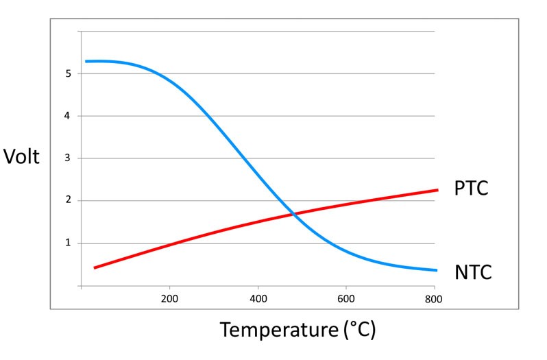
An electrical resistor is installed in the measuring tip of the exhaust gas temperature sensor, the value of which changes depending on the temperature. These resistors are called thermistors and are divided into two groups. Here a distinction is made between NTC thermistors and PTC thermistors, depending on their temperature behaviour ( Figure 1 ).

NTC - resistor with negative temperature coefficient (the resistance decreases with increasing temperature)

PTC - resistor with positive temperature coefficient (the resistance increases with increasing temperature)

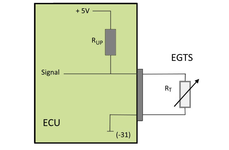
The exhaust gas temperature sensor (EGTS) is usually connected directly to the engine control unit (ECU). Together with another resistor (RUP) in the control unit, the sensor forms a series connection through which an electrical voltage is divided. The signal is measured at the voltage divider and converted into temperature information by an algorithm ( Figure 2 ).

2. Effects

Exhaust gas temperature sensor - Symptoms

The following effects can occur in the event of an exhaust gas temperature sensor failure:

  • Warning lamp for glow plug system flashes
  • Warning lamp for particulate filter lights up
  • Engine control lamp is on
  • Increase in exhaust emissions (CO, NOx and HC)
  • Poor driving behaviour because of shortened regeneration intervals of the particulate filter 
  • Increased fuel consumption caused by longer particulate filter regeneration
  • Loss of performance caused by incorrect detection of the degree of saturation of the particulate filter
3. Causes of failure

Exhaust gas temperature sensors - defective

The following causes can be responsible for the failure of the exhaust gas temperature sensor:

  • Power supply faulty
  • External damage
  • Internal damage to the electrical wiring caused by strong vibrations in the exhaust gas system
  • Excessively high exhaust gas temperatures as a result of defects in the injection system or in the air-fuel mix
4. Troubleshooting

Checking the exhaust gas temperature sensor

System overview

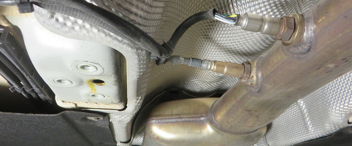
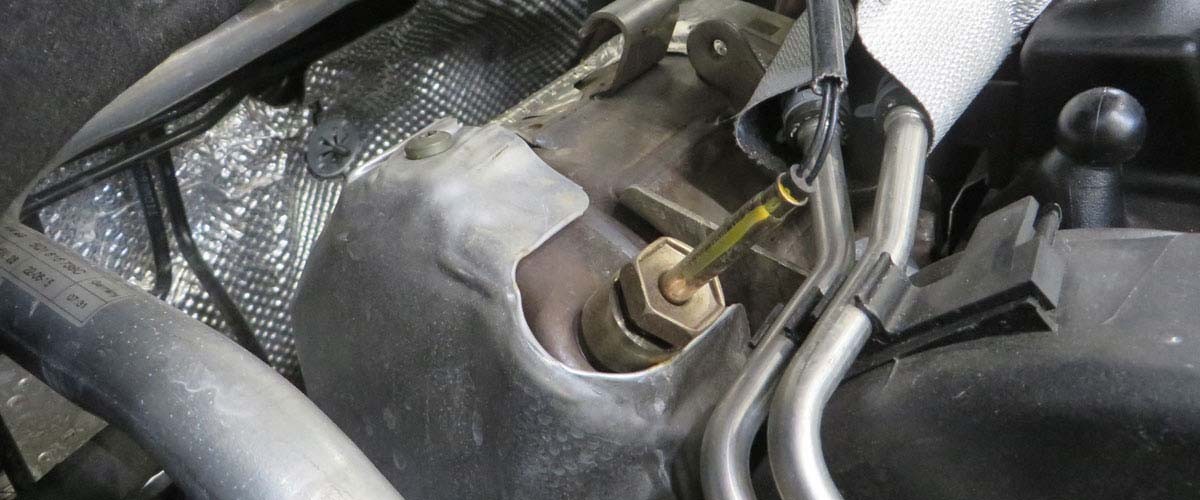
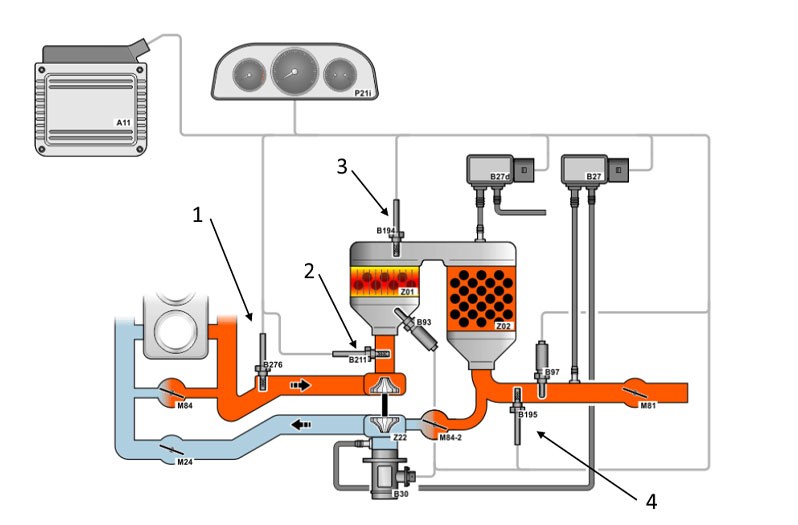
The following information is illustrated using a VW Passat 2.0 16 V TDI from the year 2015 as an example. Depending on the vehicle features, up to four exhaust gas temperature sensors can be installed. Engine control monitors the temperature before the catalytic converter, turbocharger and also upstream and downstream of the diesel particulate filter.

In vehicles without a SCR (Selective Catalytic Reduction) catalytic converter, the exhaust gas temperature sensor behind the diesel particulate filter is not required. In the event of a defective exhaust gas temperature sensor or in the case of implausible output values, the system switches to emergency operation or alternatively uses a substitute value to protect the relevant components from overheating. An error entry is then recorded in the engine control unit and the warning lamp in the dashboard is activated.

Testing with the diagnostic unit

The function of the exhaust gas temperature sensor is monitored by the respective higher-level system control unit. Any errors that occur are stored in the error memory of the control unit and can be replaced by using a suitable diagnostic unit. Depending on the system, additional parameters can be displayed and used for troubleshooting.

1

Error code

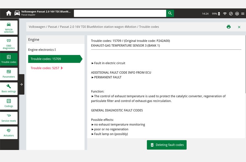
In this function the error codes stored in the error memory can be read out and deleted. In addition, information on the error code can be called up.

  • In our case study the error codes 15709 and 5257 are displayed, codes which indicate a fault in exhaust gas temperature sensor 3.
2

Parameters

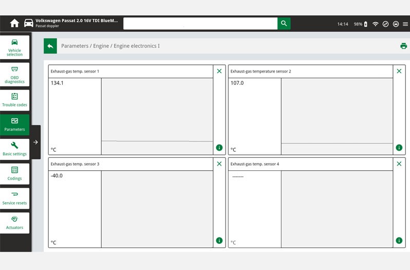
In this function, the current measured values of the sensor in the control unit can be displayed and evaluated.

  • Illustration shows a vehicle with three exhaust gas temperature sensors
  • Sensor 3 shows a value of minus 40 degrees, which may be due to an interruption in the electrical wiring or to a defect in the sensor.

3

Circuit diagrams

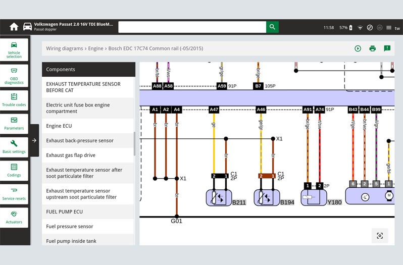
System-specific circuit diagrams can be taken from vehicle information and used for troubleshooting purposes. Here the PIN assignment on the exhaust gas temperature sensor or the cable colours can be read off and used for further tests.

Maintenance and repair instructions!

  • As part of troubleshooting, a visual inspection of the components and peripherals in the engine compartment should first be carried out after the ECU diagnosis.
  • The sensor should be replaced if the connecting cable or sensor housing is damaged.
  • If the threads of the exhaust gas temperature sensors are coated, they must not be treated with an extra coating of hot thread paste.
  • Exhaust gas temperature sensors must be tightened to the specified tightening torque! We recommend a tightening torque of 40 - 45 Nm for HELLA exhaust gas temperature sensors.

Please also observe the respective maintenance and repair instructions provided by each individual vehicle manufacturer!

Important!

The various diagnostic options have been illustrated using the mega macs 77 diagnostic unit as an example. The respective test depth and variety of functions can be set out differently depending on the vehicle manufacturer and is dependent on the relevant system configuration of the control unit.

Schematic illustrations, pictures and descriptions serve to explain and illustrate the document text and cannot be used as a basis for vehicle-specific repairs.

أداة البحث عن قطع الغيار
ذهاب فقط التعرف اليدوي على المركبات قطع غيار عالمية
أبرز الشركات المصنعة
شركات تصنيع أخرى
سلسلة المركبات العودة
مركبة العودة

أدخل رقم OE في حقل الإدخال. عادةً ما تجد رقم OE على قطعة الغيار نفسها أو في مستندات السيارة.

أداة البحث عن قطع الغيار
التعرف البسيط على المركبات كما يجب تحديد قطع الغيار باستخدام أرقام المعدات الأصلية معلومات تفصيلية عن المنتج ابحث عن تجار الجملة بالقرب منك
dummy
Processing Selected Car
الشركة المصنعة
سلسلة المركبات
مركبة
قدرة المحرك
سعة المحرك
نوع الوقود
سنة البناء
رمز المحرك

اختر الفئة:
العودة
dummy
شارك
إرسال عبر نسخ الرابط
تم نسخ عنوان URL إلى لوحة النسخ!
رقم المادة
Number
تم نسخ رقم المنتج!
البحث في الويب تعليمات التركيب
مزيد من التفاصيل
الاسم القيمة
تفاصيل أقل

الموزع الخاص بك

ما مدى فائدة هذا المقال بالنسبة لك؟

غير مفيد على الإطلاق
5
4
3
2
1
مفيد جدًا
Success

كابتشا غير صحيحة

كابتشا غير صحيحة

Error

حدث خطأ ما

You might also be interested in

نظام مراقبة ضغط هواء الإطارات TPMS
المعرفة الأساسية
نظام مراقبة ضغط هواء الإطارات TPMS
نظرة عامة على أنظمة مراقبة ضغط الإطارات المباشرة وغير المباشرة (TPMS) - كل ما تحتاج إلى معرفته لمركز صيانة المركبات.
وقت القراءة: 15 دقيقة
 نظام مساعد القيادة المتقدم ADAS
المعرفة الأساسية
العنوان: نظام مساعد القيادة المتقدم ADAS والقيادة الذاتية: نظرة عامة للورش
كل المعلومات عن  نظام مساعد القيادة المتقدم ADAS والقيادة الذاتية: الوظائف، وتكامل المستشعرات، والذكاء الاصطناعي، وأجهزة التشخيص - شرح موجز لمحترفي السيارات والوِرش.
وقت القراءة: 13 دقيقة
وسائل النقل الكهربائية
المعرفة الأساسية
وسائل النقل الكهربائية في العمل اليومي للورشة: التقنيات والمتطلبات
انتشار وسائل النقل الكهربائية يغير تفاصيل العمل في الورشة: تعرّف على كيفية تعامل الورش مع أنظمة الجهد الكهربائي العالي، وإجراءات التشخيص الجديدة، وبرامج التأهيل المُوجه.
وقت القراءة: 17 دقيقة
عرض عام لأنظمة مساعدة السائق
المعرفة الأساسية
معلومات عن أنظمة مساعدة السائق في السيارة | هيلا
نظرة عامة على أنظمة مساعدة السائق: من نظام تثبيت السرعة التكيفي والشعاع العالي الخالي من الوهج إلى تحذير مغادرة المسار - كل شيء للورشة.
وقت القراءة: 2 دقيقة
مستشعر أكسيد النيتروجين
المعرفة الأساسية
مستشعر اكسيد النتروجين - نصائح لاستكشاف الأخطاء وإصلاحها
كل ما يتعلق بمستشعر أكسيد النيتروجين (NOx): كيفية عمله، الأسباب الشائعة للأعطال، الأعراض وتشخيص الأعطال باستخدام وحدة التحكم.
وقت القراءة: 8 دقيقة
صيانة وتشخيص أعطال مستشعر الرادار بتردد ٧٧ جيجاهرتز
المعرفة الأساسية
صيانة وتشخيص أعطال مستشعر الرادار بتردد ٧٧ جيجاهرتز
اكتشف كيف يدعم مستشعر رادار هيلا بتردد ٧٧ جيجاهرتز أنظمة مساعدة السائق ويحدد الأجسام بدقة في جميع الظروف الجوية. تعرف على تصميمه ووظائفه وتطبيقاته في السيارة.
وقت القراءة: 6 دقيقة
حساس دعسة البنزين | الوظيفة ,الهيكل وتشخيص الأعطال | هيلا
المعرفة الأساسية
حساس دعسة البنزين | الوظيفة ,الهيكل وتشخيص الأعطال | هيلا
نصائح مهمة لفحص مستشعر دواسة الوقود وإصلاح الأعطال - معلومات عملية لورشة العمل الخاصة بك.
وقت القراءة: 3 دقائق
فوهة الحقن / صمام الحقن - الوظيفة والفحص
المعرفة الأساسية
فوهة الحقن / صمام الحقن - الوظيفة والفحص
تعرف على كيفية تشخيص عطل في حاقن الوقود واستبداله في ورشة الصيانة.
وقت القراءة: 4 دقائق
مستشعر الخبط - الوظيفة، وتقصي الأخطاء
المعرفة الأساسية
مستشعر الخبط - الوظيفة، وتقصي الأخطاء
تعرف على كيفية فحص مستشعر الاهتزاز للتأكد من عدم وجود أعطال، وكيفية معالجة أعراض الأعطال المحتملة.
وقت القراءة: 2 دقيقة
فحص وتغيير مستشعر ABS - التعليمات
المعرفة الأساسية
فحص وتغيير مستشعر ABS - التعليمات
إرشادات لتشخيص أعطال مستشعر نظام ABS واستبداله - جميع الخطوات اللازمة لإجراء إصلاح احترافي.
وقت القراءة: 9 دقيقة

Quick question

رائع! لم يتبق سوى خطوة واحدة

تم الاشتراك بنجاح

انتقل إلى صندوق الوارد الخاص بك وقم بتأكيد عنوان بريدك الإلكتروني حتى لا تفوتك آخر أخبارنا!

استعد لمشاهدة مقاطع فيديو تقنية جديدة تمامًا، ونصائح حول إصلاح السيارات، ودورات تدريبية، ونصائح تشخيصية مفيدة، وحملات تسويقية، وغير ذلك الكثير... يتم إرسالها مباشرة إلى بريدك الإلكتروني كل أسبوعين!