Lane change assist

Here you will find useful knowledge and handy tips relating to the lane change assistant and blind spot assistant.

As driver assistance systems for preventing accidents continue to develop, there is more and more interest in radar sensors for assistance systems to the rear of the vehicle. An increasing number of vehicle models are being equipped with these sensors as standard. Sooner or later, the issue of diagnostics and repairs will therefore become part of everyday workshop life not just for brand workshops but independent ones too. In this article, we want to concentrate in particular on the issue of radar sensors for rear applications and their use in the "lane change assistant" driver assistance system.

Important safety note The following technical information and practical tips have been compiled by HELLA in order to provide professional support to vehicle workshops in their work. The information provided on this website is intended for use by suitably qualified personnel only.


RADAR SENSORS IN DRIVER ASSISTANCE SYSTEMS: GOOD TO KNOW

More and more driver assistance systems are increasingly being fitted with radar sensors for driver assistance. One advantage of this technology is that radar sensors can achieve a precise measurement result regardless of the weather. For the main part, people associate the word "radar" with aviation or shipping. These systems have long become established and proven themselves in such applications. "Radar" is the abbreviation for Radio Detection and Ranging.


Put simply, a radar unit transmits focused electromagnetic waves, known as primary signals, at the speed of light. When these waves encounter an object, they are reflected as echoes (secondary signals) and received and evaluated by the system. Direction, distance and speed can then be determined in the system's evaluation electronics.

Use in the automotive sector

Radar sensors are used in various assistance systems to measure distance in driver assistance systems at the front and rear. 


Radar sensors for front applications, such as adaptive cruise control (ACC), have been available in various vehicles for several years now. 


As driver assistance systems for preventing accidents continue to develop, there is more and more interest in radar sensors for assistance systems to the rear of the vehicle. An increasing number of vehicle models are being equipped with these sensors as standard. Sooner or later, the issue of diagnostics and repairs will therefore become part of everyday workshop life not just for brand workshops but independent ones too.

HELLA 24 GHZ RADAR SENSORS: BASICS

HELLA has been producing radar sensors in the 24 GHz narrow-band range for more than a decade. HELLA put its first generation of 24 GHz radar sensors into serial production back in 2005. The sensor systems are ideal for applications that have since become standard functions, such as blind spot detection, lane change assistants and rear-facing parking assistance.


The sensor records speed, angle and distance information for objects within a distance of up to 70 m behind the vehicle and then evaluates the information. The LFMSK (Linear Frequency Modulation Shift Keying) process has been used since the first generation of devices.


This process can be used to sense and determine the distance and relative speed of several objects with just one signal (chirp), the frequency of which changes over time.


In the third generation of radars, an enhanced FM variant is used. Here the modulation bandwidth is limited to max. 200 MHz. The system operates at an average transmission power of 13 dBm (EIRP) in a frequency range of between 24.05 and 24.25 GHz. The resultant spatial resolution of 0.75 m is suited to the rear-end functions undertaken. The monopulse method is used here to determine the angle. On the basis of specific signal-processing approaches, the system uses various receive paths to compare the phases of the radar reflections.


Another safety function, the exit assistant, is integrated in the fourth generation radar sensors. This detects dangerous situations, such as passing cars, before exiting the vehicle and warns all passengers.

THE ADVANTAGES OF THIS SENSOR TECHNOLOGY ARE:

  • The small installation size and excellent transmission properties of 24 GHz technology allow these sensors to be fitted or integrated hidden behind the bumper
  • Frequency modulation and antenna size are ideally harmonised
  •  Mature mass production of products, functions and installation
  • Ideal value for money compared to other radar technologies 
TECHNICAL DATA
Measuring principle LFMSK (Linear Frequency Modulation Shift Keying) process
Frequency range 24.15 GHz/ISM
Bandwidth <= 200 MHz/ISM
Transmission efficiency <= +20 dBm peak, EIRP
Cycle time 1.5 m with 200 MHz OBW

Speed measurement

         Relative speed interval
         Separability


-70 m/s to +70 m/s
0.32 m/s

Sensing area azimuth 165°

Depending on the sensor generation, the following applications can be integrated:

Blind spot monitoring

This function monitors the area in the driver’s blind spot and warns him or her of danger when changing lanes. The sensor operates in the near range.

Lane change assistant

The lane change assistant makes driving safer by warning if a lane change is a dangerous manoeuvre. A warning distance of 70 m gives the driver enough time to abort the lane change.  This function ensures maximum safety when driving on highways. 

REAR PRE-CRASH SYSTEM

The rear pre-crash system tracks vehicles approaching from behind and, in the event of an imminent collision, pre-activates safety devices such as airbags, seat belts etc.

REAR CROSS TRAFFIC ALERT

The rear cross traffic alert warns the driver of approaching vehicles when manoeuvring out of a parking space. The function is activated by selecting reverse gear and is based on the radar sensor’s side detection capability.

VEHICLE EXIT ASSISTANT

The vehicle exit assistant monitors the area to the right and left of the car doors; both on the passenger's and the driver's side at the front and back. The function warns the occupants if the car door cannot be opened safely.

LANE CHANGE ASSIST: STRUCTURE AND FUNCTION

One technical innovation within driver assistance systems is the lane change assistant. This assistant informs the driver of potential hazards when changing lane on roads and highways with several lanes. It serves to prevent accidents and therefore helps to improve safety on the road. 


In this section, the following pieces of system information are outlined taking the "Audi Side Assist" driver assistance system as an example. 

Control units

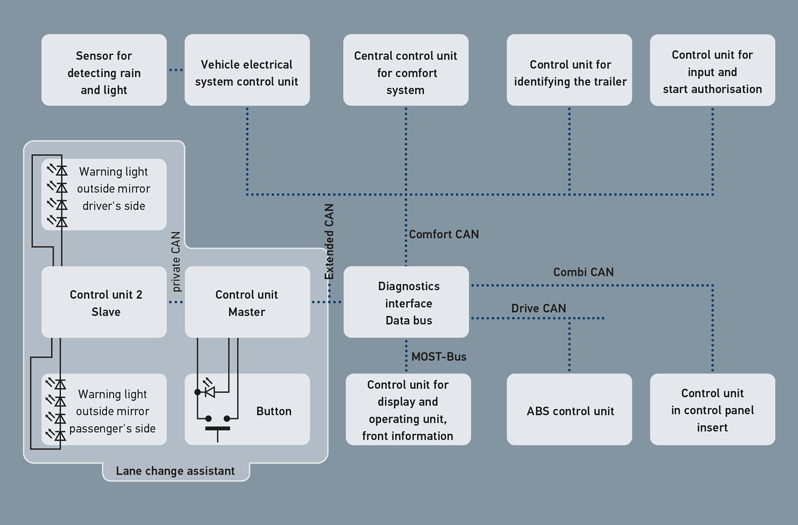
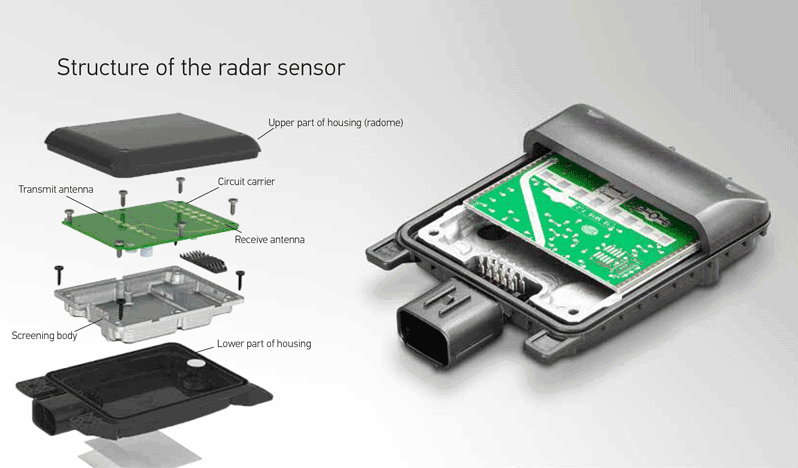
The lane change assistant system consists of a master and a slave control unit with identical structures. Together with an integrated radar sensor, the two control units produce one standalone component. Above the radar sensor, the control unit is fitted with a plastic cover. This cover, also known as a "radome", is made from a special material, through which radar beams can pass perfectly.


The "master" control unit (1) is fitted behind the bumper on the left and the "slave" control unit (2) is fitted behind the bumper on the right.

Warning lights

Furthermore, the system has two 4 LED warning lights, integrated in the housings of the outside mirrors on the left and right. 

On and off switch

A button, which can be used to switch the lane change assistant function on and off, is integrated in the cover above the front left door trim panel.
The function status is indicated by an LED light integrated in the button. The system stores the last set status and adopts this status when restarted. 

Functional description of the lane change assistant

The lane change assistant "Side Assist" takes effect from a speed of 30 km/h. The sensing area (A) of the radar sensors is approx. 50 m to the rear and approx. 3.6 m (B) to the side of the vehicle. 


The system uses radar sensors to monitor the traffic behind and next to the vehicle. The area monitored includes the "blind spot" which the driver cannot see on both the driver and passenger sides.


If there is a vehicle in the monitored area and if a lane change is not taking place, the driver is informed by the LED displays in the right and left outside mirrors lighting up a little. The luminous intensity is lower so the driver is not distracted unnecessarily. In this situation, should the driver actuate the direction indicator lever for changing lane, he or she is warned by the warning lamp in the outside mirror of the corresponding side flashing intensively. 


If the system senses a vehicle, the control unit in question also calculates the time remaining before a potential collision. This evaluation is used by the system to distinguish between vehicles which are approaching, flowing with the traffic and falling behind.

APPROACHING VEHICLES

A vehicle still at some distance away can be classified as critical if it approaches at greater speed. The warning light in the mirror is activated sooner.

VEHICLES FLOWING WITH THE TRAFFIC

If vehicles flowing with the traffic are classified as critical for a lane change, the warning lamp is activated. All vehicles sensed in the "blind spot" are shown.

VEHICLES WHICH ARE FALLING BEHIND

If an object sensed with a difference in speed of less than 15 km/h is slowly overtaken by the vehicle, the warning light is activated as soon as the object is in the blind spot. If the vehicle is overtaken at a speed of more than 15 km/h, the driver is not warned.

CORNERING

If the radius of the corner is more than 170 m, vehicles are detected by the system in the area to the rear. If the corner radius is less than this, the lane change assistant is passive because the sensors are no longer able to sense the entire monitoring area of 50 m behind the vehicle.

FURTHER FUNCTIONS

Trailer operation
When an electrical connection is made with a trailer socket fitted in the workshop, the lane change assistant automatically switches off. 


Adjusting display brightness of warning light
The brightness of the warning light is automatically adjusted by the system. The system receives information about the adjustment via the rain/light sensor. However, the driver can adjust the brightness to his or her requirements in the Multi Media Interface (MMI). If the upper or lower control limits are reached by the automatic adjustment, further adjustments are not possible. The adjustment values are personalised to the respective vehicle key. 

COMMUNICATION AND SYSTEM INTEGRATION: OVERVIEW

In order to calculate the driver information about a potential hazard situation, the lane change assistant needs numerous pieces of information. The control unit receives the information required from various sources.
The master and slave control units are linked to one another via a dedicated high-speed CAN data bus. The data exchange takes place at a transfer speed of 500 kBit/s. For further communication in the vehicle, the master control unit is linked to the diagnostics interface in order to communicate with other bus users. 

Unit Information
Control panel control unit Optical and acoustic driver information about faults
Rain/light sensor Informs the master control unit about the ambient lightness currently being measured in order to adjust the warning lights
ABS control unit Information about wheel speed and yaw rate
Control unit for identifying the trailer Trailer operation information
Lane tracking assistant button Lane tracking assistant information "On or Off"
Comfort central control unit
  • Lane change information when direction indicator is actuated
  • "Reverse travel" information when reverse gear is engaged
Start authorisation for control unit Information about input start authorisation and key information
Control unit for display and operating unit "Warning lights brightness" driver's request

Driver information in the instrument cluster

Should the system shut down, the following information is shown in the instrument cluster's display:


Information in the display Cause
Audi Side Assist not available: Sensors blocked The operating range and/or view of the sensors is blocked by a bike rack or similar.
Audi Side Assist: System fault Due to a defective sensor, the system is no longer able to guarantee a safe function and shuts down.
Audi Side Assist: Not available at present Temporary shutdown due to a defective battery or insufficient charge condition.
Audi Side Assist: Not available in trailer operation Trailer operation was detected.

Functional limitations

The radar system is designed so that all travel situations on lanes of a normal width with one left and one right lane are covered. Despite this, there are some scenarios where the system may activate the warning lamp in the mirror even though there are no vehicles in the area critical to lane changes. 


Example situations provided by the vehicle manufacturer:

  • If the driver is driving very close to the edge of narrow roads and vehicles on another lane are detected
  • On tight bends, the system may respond to a vehicle on the next but one lane
  • Response to guard rails or other objects, that are too high or offset
  • Functional limitations resulting from very bad weather
NOTE

For the lane change assistant to work perfectly, the bumper near the radar sensors must not be covered or bonded. In the winter, these areas should also be kept free of snow and ice.

DIAGNOSTICS AND REPAIR INSTRUCTIONS FOR THE LANE CHANGE ASSIST: VIDEO

Service work on the radar sensor - Audi Side Assist

In this video, we show you diagnostics and repair instructions for the "lane change assistant" driver assistance system.


03:41 min

SERVICE WORK ON THE LANE CHANGE ASSIST: DIAGNOSTICS

Diagnostics

The system functions of the lane change assistant are monitored continuously. Any errors which occur are stored in the control unit's error memory and can be read using a suitable diagnostic unit. Depending on the system, additional parameters can be displayed and used for troubleshooting. 


The following diagnostics functions can be used as part of troubleshooting:

Fault code

In this function, the fault codes stored in the error memory can be read out and deleted. Information about the fault code can also be called up.

Reading out parameters

In this function, the current measured values of the control unit are displayed.

Performing an actuator test

  • Component activation by the control unit in the electronic systems
  • Check basic function and cable connection of components

Coding

  • In this function, new components or additional functions can be released and/or coded in a system.
  • Coding of actuators or control units after replacement on the vehicle

Control unit identification

Special system and control unit information can be called up here.

NOTE

The various diagnostic options have been shown on the mega macs 66 diagnostic unit by way of example. The respective extent of testing and variety of functions depend on the respective system configuration of the control unit.

Calibration

To ensure that the lane change assistant works safely, it must be adapted after the following work:

  • If one or both control units have been replaced
  • If repair work has been carried out on the body at the rear
  • If the position of the rear bumper has been changed
  • If the mounting position of the control units has been changed due to fitting and removal


Calibrating the system requires not just a diagnostic unit but also a Doppler generator and a calibration panel. The test tools are arranged behind the vehicle as specified by the vehicle manufacturer. The Doppler generator simulates a moving object. The calibration process is started by the diagnostic unit and follows specified operating sequences. Within this fully automatic sequence, the control unit detects the correction values needed from the actual and target position and stores them for future distance measurements. 

REPAIR NOTES

The bumper may only be painted using paints approved by the vehicle manufacturer. Non-approved paints may result in a restricted or incorrect function. To assist the vehicle electrical system during service work on the vehicle, connect a suitable charger. Please observe the relevant maintenance and repair notes provided by the vehicle manufacturer! 

How helpful is this article for you?

Not helpful at all

Very helpful

Please tell us what you did not like.
Many thanks. But before you go.

Sign up for our free HELLA TECH WORLD newsletter to receive the latest technical videos, car repair advice, training course information, marketing campaign details and diagnostic tips.

Show additional information on our newsletter Hide additional information on our newsletter

Register for our free HELLA TECH WORLD newsletter to stay up-to-date with the latest technical videos, car repair advice, trainings, diagnostic tips and marketing campaigns.

Together we can get cars back on the road quickly!

Please note:
You will only be subscribed to the newsletter once you have clicked on the confirmation link in the notification e-mail you will receive shortly!

Data Protection | Unsubscribe

Please note:
You will only be subscribed to the newsletter once you have clicked on the confirmation link in the notification e-mail you will receive shortly!

Data Protection | Unsubscribe

Almost There!

All you need to do is confirm your sign up!
We've sent an e-mail to your email address.

Check your inbox and click on the confirmation link to start receiving HELLA TECH WORLD updates.

Wrong e-mail or no confirmation received?
Click here to enter it again.