Exhaust gas aftertreatment: Design, function and diagnostics

Here you will find valuable and useful workshop tips about the design, function and diagnostics of exhaust gas aftertreatment.

Important safety note
The following technical information and practical tips have been compiled by HELLA in order to provide professional support to vehicle workshops in their work. The information provided on this website is intended for use by suitably qualified personnel only.


Design and function of exhaust gas aftertreatment: Basics

Exhaust gas aftertreatment refers to the processes that clean exhaust gases mechanically, catalytically or chemically after they have left the combustion chamber.


Aftertreatment is carried out to convert the pollutants produced during combustion into harmless exhaust gases. Exhaust gas aftertreatment components include catalytic converters and particulate filters. Nowadays, both components can be installed on a direct-injection petrol engine as well as on a diesel engine.


The following systems, for example, can be installed in the exhaust system to reduce pollutants:


Petrol engine

  • Three-way catalytic converter
  • NOx absorber (lean-burn engines)
  • Otto particulate filter (engines with direct injection)


Diesel engines

  • Oxidation catalytic converter
  • Particulate filter
  • NOx absorber
  • SCR catalytic converter

Catalytic converter

The catalytic converter usually used in conventional petrol engines today is the controlled three-way catalytic converter. The task of the catalytic converter is to convert the pollutants originating from the fuel combustion process into non-toxic exhaust gases by means of a chemical reaction. In conjunction with the engine control unit and lambda sensor, the air/fuel mix is precisely regulated so that the catalytic converter can reduce the pollutants. The optimal working temperature range of catalytic converters is between 400-800°C.

Design

The catalytic converter consists of a honeycomb-shaped ceramic or metal body with several thousand channels. An intermediate layer, (wash coat) made of aluminium oxide is applied to the channels, which enlarges the surface approximately 7000 times. In addition, a catalytic layer with the precious metals rhodium, palladium and platinum is vapour-deposited on the intermediate layer. In the stainless steel housing, the catalytic converter is fixed in place by an insulation mat, which compensates for thermal expansions at the same time.

Mode of operation

The harmful exhaust gases from the engine are fed to the catalytic converter via the exhaust manifold and flow through the channels of the ceramic or metallic carrier. A chemical reaction is triggered when the exhaust gases make contact with the catalytic layer.


Carbon monoxide and hydrocarbons are oxidised to carbon dioxide on the precious metals platinum and palladium, and nitrogen oxides are reduced to nitrogen (N2) on rhodium. The term three-way catalytic converter means that three chemical conversions take place simultaneously side by side as soon as the operating temperature is reached. Thus, carbon monoxide (CO), hydrocarbons (HC) and nitrogen oxides (NOx) are converted into nitrogen (N2), carbon dioxide (CO2) and water (H2O).


The function of the catalytic converter is monitored by a second lambda sensor, also called an oxygen sensor, behind the catalytic converter. This oxygen sensor measures the oxygen content in the exhaust gas stream and transmits the measured value to the control unit. The control unit compares the values of the upstream (pre) and downstream (post) catalytic converter sensors to evaluate the converter’s functioning. If both values are almost identically high, it can be concluded that the catalytic converter has a low oxygen storage capacity, meaning that the catalytic converter is defective.

Topical videos

Catalytic converter

In our video crash course, we give you an all-round look at the topic of catalytic converters

Diesel particulate filter

Particulate filters are installed in the exhaust system of diesel engines to reduce soot emissions. The diesel particulate filter (DPF) stores the solid particles that cannot be completely burnt in the engine. These nanoparticles, reduced in size, are very harmful to humans and the environment. The inside of the soot particulate filter consists of a ceramic filter with many small channels. The channels with porous walls are alternately closed and divided into inlet and outlet channels. The exhaust gases flow through the filter walls, whereby the soot particles are deposited on the filter walls. The porous walls produce a good filtering effect and a high degree of separation. The increasing number of accumulated soot particles increases the back pressure in the exhaust system. The degree of loading or flow resistance of the particulate filter is monitored by the engine control unit. A differential pressure sensor records the data upstream and downstream of the particulate filter and passes this information on to the engine control unit. If the pressure difference exceeds a certain value, the control unit initiates regeneration to burn off the particles.


In order for the soot particles to be burnt off, the exhaust gas temperature in the particulate filter must be raised to 600 - 650°C. For this purpose, the engine control system carries out additional fuel injection or post-injection during active regeneration, which increases the exhaust gas temperature.


Depending on the vehicle and system, regeneration can be carried out every 400-700 km.


To avoid temperature ranges above 700°C, the temperature is monitored by an exhaust gas temperature sensor just upstream of the particulate filter.


The ash produced during regeneration is not completely removed by the exhaust gas flow, so it accumulates in the filter. This can lead to the filter becoming clogged and needing to be cleaned or replaced. This leads to the filter having change intervals, e.g. every 120,000 km.

Please note

To calculate the soot loading of the soot particle filter, the engine control unit uses signals from the differential pressure sensor, the temperature sensors upstream and downstream of the soot particle filter and the mass air flow sensor. Therefore, the signals are considered as one unit.

Topical videos

Diesel particulate filter

A little knowledge refresher is provided in the video: You will be guided through facts on structure and function as well as appropriate test procedures. Our common goal: reducing emissions!

Regeneration

Depending on the vehicle manufacturer and system, various particulate filter regeneration procedures can be carried out.


Passive regeneration
Passive regeneration takes place as soon as the exhaust gas temperatures in the particulate filter reach a value of 350 - 500°C on motorway journeys at increased speeds.


Active regeneration
Active regeneration is carried out by the engine management system. When the load limit of the particulate filter is reached, the exhaust gas temperature is specifically raised to 600-650°C via the engine control unit in order to burn off the soot particles.


Forced regeneration
This type of regeneration can be carried out by a workshop using a diagnostic device in accordance with specified instructions.

Combined particulate filter

A soot particulate filter and oxidation catalytic converter can be installed in one housing as a catalytically coated diesel particulate filter. In this combination, the catalytic converter is installed before the soot particulate filter. It combines the function of a diesel oxidation catalytic converter and diesel particulate filter in one component. As a result, hydrocarbons (HC) and carbon monoxide (CO) can be converted into water (H2O) and carbon dioxide (CO2) and soot particles can be filtered out of the exhaust gas. Another of the oxidation catalytic converter's tasks is to change the ratio of nitrogen (NO) to nitrogen dioxide (NO2) to enable passive regeneration of the DPF filter and increase the performance of the SCR catalytic converter. As the exhaust gases flow through the catalytic converter, chemical processes increase their temperature. Heat is transferred to the soot particulate filter with the exhaust gas flow. This means that the catalytic converter helps heat the soot particulate filter.

NOx absorber

The NOx absorber is used in diesel and direct-injection petrol engines. The catalytic converter has a catalytic layer of substances such as potassium oxide or barium oxide that bind nitrogen oxide molecules. As soon as the absorber has reached a certain absorption capacity, the engine control system greases the air-fuel mixture, increasing the exhaust gas temperature. The changed exhaust gas composition leads to regeneration, which sees the nitrogen oxides (NOx) reduced to nitrogen (N2) and water (H2O).

SCR catalytic converter

Selective catalytic reduction (SCR) is one of the latest and most advanced developments in exhaust gas reduction for cars. This technology has been in use since 2014 and meets the EURO 6 emission standards. By adding carbamide (AdBlue) to the exhaust gas stream, the nitrogen oxides (NOx) are converted to nitrogen (N2), water vapour (H2O) and a small amount of CO2 in the NOx absorber by selective catalytic reaction. A NOx absorber is designed like an oxidation catalytic converter.

Exhaust gas aftertreatment sensors

Modern exhaust gas aftertreatment systems not only consist of the components of the exhaust system, but also require various sensors to monitor the exhaust gas composition and pass on their information to the engine control unit.

Lambda sensor

The lambda sensor determines the residual oxygen content in the exhaust gas and provides the engine control unit with an electrical signal to regulate the mixture composition. Optimum combustion is required if an ideal conversion rate is to be ensured for catalytic converters. On petrol engines, this is achieved with an air-fuel ratio of 14.7 kg air to 1 kg fuel (stoichiometric mix). This optimum ratio is designated by the Greek letter λ (lambda). Lambda is used to express the air ratio between the theoretical air requirement and the actual air volume supplied:


λ = supplied air volume: theoretical air volume = 14.7 kg : 14.7 kg = 1

Exhaust gas temperature sensor

In modern vehicle models, exhaust gas temperature sensors are installed at various points in the exhaust gas system in both diesel and petrol vehicles. The exhaust gas temperature sensor detects the temperature, for example upstream of the catalytic converter or diesel particulate filter, and sends this as a voltage signal to the engine control unit. The engine control unit needs this information in order to control the air-fuel ratio or the particulate filter regeneration and thus to effectively reduce emissions. In addition, high temperature sensors help to protect components in the area of ​​the hot exhaust gas flow from critical overheating.

Differential pressure sensor

The exhaust gas pressure sensor ─ also referred to as the differential pressure sensor ─ is required on diesel engines in order to monitor the particulate filter system. Increasing accumulations of soot and ash alter the differential pressure in the particulate filter. The differential pressure sensor measures the pressure difference between the exhaust gas on the inlet and outlet side of the particulate filter. This measured value is required by the electronic engine control system as additional information to calculate the regeneration, or purging time, of the particulate filter. This sensor is therefore another element in the systems for regulating pollutant emissions for diesel engines based on European emission regulations.

Nitrogen oxide sensor

The NOx sensor comprises a probe and a control unit. These are firmly connected together using a cable harness to form a unit. This sensor unit is installed in the exhaust gas system and is used to recognise nitrogen oxides in the flow of exhaust gas. The NOx sensor is an important component in the aftertreatment system to reduce NOx. It is used in diesel vehicles with carbamide-based SCR systems (selective catalytic reduction) and guarantees that strict Euro 5 emissions values are observed. Consequently the NOx sensor enables the engine system to provide an optimal dosage of AdBlue, effectively reducing nitrogen oxides, which are harmful to the environment. If the SCR system has an upstream and a downstream NOx sensor, the downstream one monitors the effect of the SCR catalytic converter.

Diagnostics for the exhaust system: Troubleshooting

Before starting control unit diagnostics on the vehicle, a visual inspection of the entire exhaust system should be carried out first. External damage can usually be detected when the noise behaviour changes and can be caused by cracks or rusting through at pipes, connections or mufflers. Noises coming from inside the system components can be localised by shaking or knocking on the relevant component. Of course, the tight screw connections, radiator plates and rubber mountings should also be checked as part of this. The exhaust gas sensors should not be forgotten either. They may be mounted over the entire course of the system. Wiring or electrical plug connections may have been damaged here due to environmental influences such as dirt, water or road salt.

Control unit diagnostics

The function check can only be carried out on the injection system or the exhaust gas aftertreatment system with a suitable diagnostic device.


The function of the individual exhaust gas aftertreatment components is monitored via sensors and transmitted to the relevant higher-level system control unit. Any errors that occur are stored in the engine control unit's error memory and can be read using a suitable diagnostic unit. Depending on the vehicle and on the system, additional functions, such as parameters or actuator tests, can be selected and displayed or executed on the diagnostic device. The data from control unit communication forms the basis for actual troubleshooting and for successful repair work. In addition, the exhaust gas values can be checked and evaluated using a tailpipe measurement.


The following diagnostic information uses a Mercedes-Benz E350 24V CDI (212) and a Volkswagen Golf 5 Plus as examples.

Reading out the engine control system’s error memory

In this function, the error codes stored in the error memory can be read out and deleted. In addition, information on the error code can be called up.


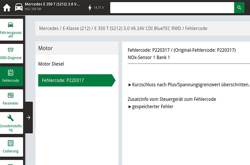
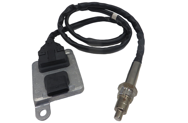
In our case study, a defective NOx sensor was detected and, as a result, the error code P220317 was stored in the error memory.


  • P220317 / NOx sensor 1 Bank 1
  • Short circuit to positive / voltage limit exceeded

Reading off parameters

In this function, current measured values such as engine speed, temperature or the status of individual exhaust gas components can be selected and displayed.


  • SCR catalytic converter / NOx sensors
  • Comparison of function test on catalytic converter / lambda sensors
  • Charge status of particulate filter / differential pressure sensor

System information

System-specific information can be taken from vehicle information and used for troubleshooting purposes. Here, for example, a system overview of the exhaust gas aftertreatment system can be used for further troubleshooting.

Exhaust tailpipe measurement

With the exhaust tailpipe measurement, the escaping exhaust gases can be recorded and evaluated directly at the exhaust system. Defects in the exhaust system or in the exhaust gas aftertreatment system are detected and can be incorporated into further troubleshooting.

How helpful is this article for you?

Not helpful at all

Very helpful

Please tell us what you did not like.
Many thanks. But before you go.

Sign up for our free HELLA TECH WORLD newsletter to receive the latest technical videos, car repair advice, training course information, marketing campaign details and diagnostic tips.

Show additional information on our newsletter Hide additional information on our newsletter

Register for our free HELLA TECH WORLD newsletter to stay up-to-date with the latest technical videos, car repair advice, trainings, diagnostic tips and marketing campaigns.

Together we can get cars back on the road quickly!

Please note:
You will only be subscribed to the newsletter once you have clicked on the confirmation link in the notification e-mail you will receive shortly!

Data Protection | Unsubscribe

Please note:
You will only be subscribed to the newsletter once you have clicked on the confirmation link in the notification e-mail you will receive shortly!

Data Protection | Unsubscribe

Almost There!

All you need to do is confirm your sign up!
We've sent an e-mail to your email address.

Check your inbox and click on the confirmation link to start receiving HELLA TECH WORLD updates.

Wrong e-mail or no confirmation received?
Click here to enter it again.