


Spare Parts Finder
OE-No.
Manual Vehicle Identification
Universal Parts

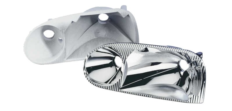
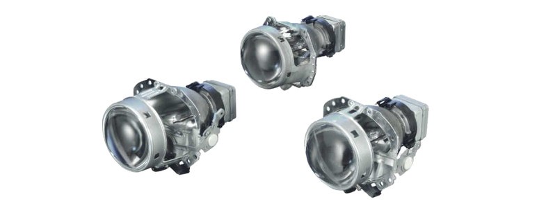
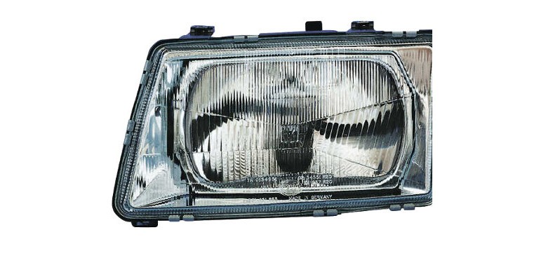
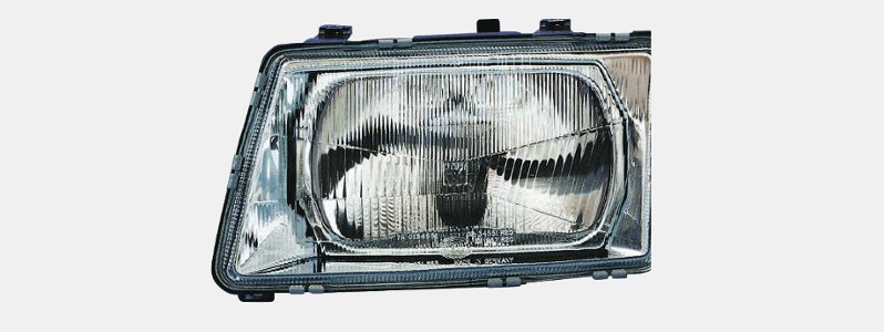
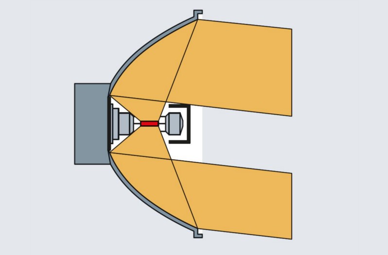
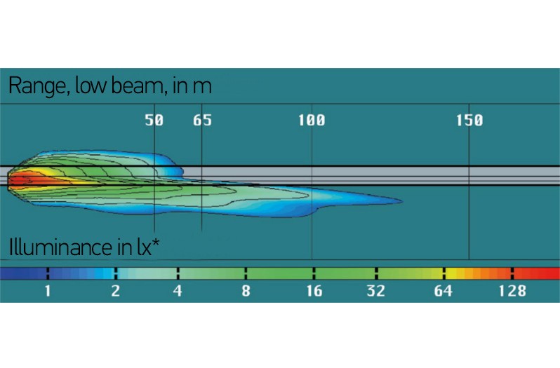
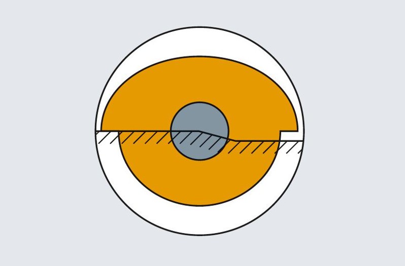
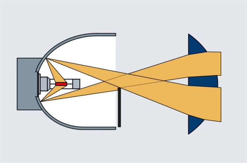
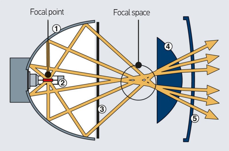
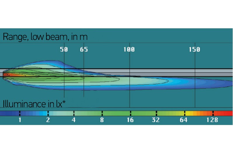
Vehicle headlamps focus the light beams generated by the light source onto the road. On this page, find out about the structure of headlamps, and what lighting technology concepts and legal regulations there are, amongst other things. Here you can also find useful practical tips for dealing with plastic cover lenses.
| Headlamps for low beam | |
| Number | Two |
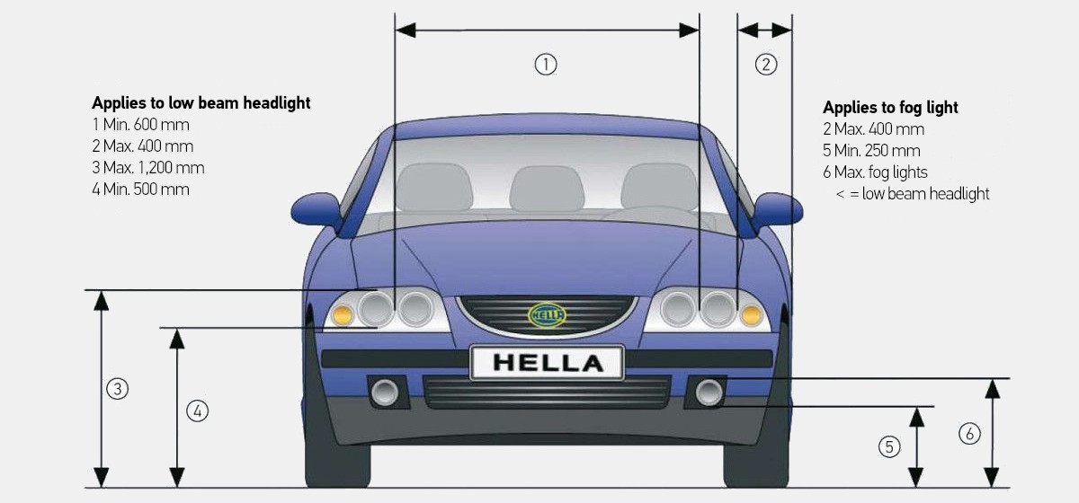
| Width position | Max. 400 mm from the outermost point |
| Height position | 500 to 1200 mm permissible |
| Electrical circuit | Switching on pairs of auxiliary headlamps in addition to the low beam and/or high beam is permitted. When changing to low beam, all high-beam headlamps must switch off simultaneously. |
| Switch-on control | Green indicator lamp |
| Miscellaneous | If the headlamps are fitted with gas discharge lamps (high and low beam), automatic headlamp leveling and a headlamp cleaning system also have to be installed. These requirements also apply when such headlamps are retrofitted to vehicles already on the road if the retrofitting took place after April 1, 2000. |
| Headlamps for high beam | |
| Number | Two or four |
| Width position | No special regulations but must be installed in such a way that the driver is not disturbed by reflections. |
| Height position | No particular specifications |
| Electrical circuit | Switching on pairs of auxiliary high-beam headlamps in addition to the low beam and/or high beam is permitted. When changing to low beam, all high-beam headlamps must switch off simultaneously. |
| Switch-on control | Blue indicator lamp |
| Miscellaneous | The luminous intensity of all the switchable high-beam headlamps must not exceed 300,000 Candela. The sum of the reference numbers may not be greater than 100. |
| Headlamps for fog light (optional) | |
| Number | Two, white or light amber |
| Width position | No particular specifications |
| Height position | Not higher than the low beam headlamps, but according to ECE at least 250 mm |
| Electrical circuit | With low and high beam. Also possible with marker light if the light exit area of the fog lamp is no further than 400 mm away from the outermost point of the vehicle width. |
ECE regulation 1
ECE regulation 8, 20 (H4 only)
ECE regulation 98
ECE regulation 123
High beam
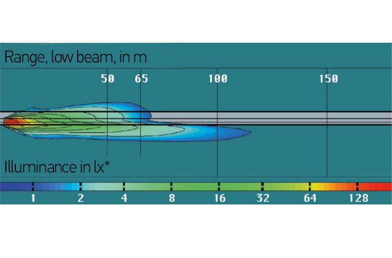
7.5; 10; 12.5; 17.5; 20; 25; 27.5; 30; 37.5; 40; 45; 50 per headlamp (in Germany max. four simultaneously switched-on high-beam headlamps are permitted, and the reference number 100 or 480 lx is the maximum value that must not be exceeded)