Brake calliper with integrated handbrake mechanism | HELLA
Assembly note for replacement brake callipers
General installation note
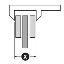
Handbrake callipers are usually set or adjusted so that the distance between the brake lining and the brake disc is at least (X) + 1 mm (fig. 1).
As vehicle manufacturers use a wide variety of different designs, they are grouped into type variants A, B, C and D within the rest of this document. Please compare the figures with the brake calliper installed in the vehicle and select the associated adjustment method.
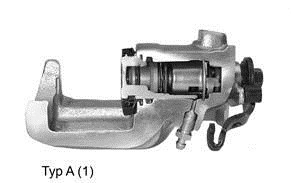
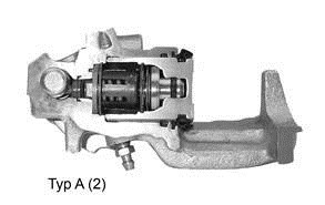
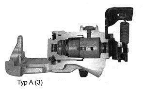
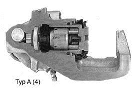
Brake calliper type A
Adjustment:
- Rotate piston, standard thread (right)
- Depending on the variant, the thread type may be left-handed or right-handed
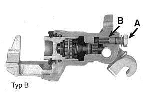
Brake calliper type B
Adjustment:
- Remove bolt A
- Adjust via hexagon screw B
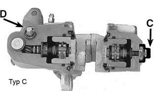
Brake calliper type C
Adjustment:
- Remove plastic cap C
- Loosen nut, adjust socket head screw, tighten nut
- Adjust hexagon screw D at the handbrake level (x = +1 mm)
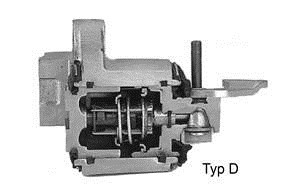
Brake calliper type D
No manual adjustment required.
Note
When performing this work, please always observe the repair instructions provided by the respective vehicle manufacturer.
Meer technische informatie
Technische productinformatie
Remvoeringslijtage indicator
Leestijd: 1 minuut
Technische productinformatie
Inrij instructie remschijven
Leestijd: 2 minuten
Technische productinformatie
Strong price increase for refrigerant R134a
Leestijd: 3 minuten
Technische productinformatie
Schadebeoordeling - Wielophanging en stuurinrichting
Leestijd: 1 minuut
Technische productinformatie
Toyota Auris - Functiebeperking door stoelverstelling
Leestijd: 1 minuut
Technische productinformatie
Slijtagegevoelige onderdelen van de wielrem
Leestijd: 2 minuten
Technische productinformatie
Reserveonderdelen met rubber delen voor remsystemen
Leestijd: 1 minuut
Technische productinformatie
Trillingsdempergewicht bij het remzadel
Leestijd: 1 minuut
Technische productinformatie
Schlag van de wielnaaf controleren
Leestijd: 1 minuut
Technische productinformatie
Schlag van de remschijf controleren
Leestijd: 1 minuut