Brake calliper with integrated handbrake mechanism | HELLA
Assembly note for replacement brake callipers
General installation note
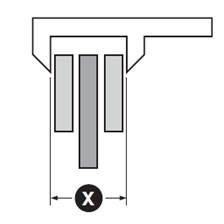
Handbrake callipers are usually set or adjusted so that the distance between the brake lining and the brake disc is at least (X) + 1 mm (fig. 1).
As vehicle manufacturers use a wide variety of different designs, they are grouped into type variants A, B, C and D within the rest of this document. Please compare the figures with the brake calliper installed in the vehicle and select the associated adjustment method.
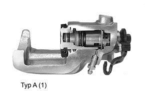
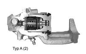
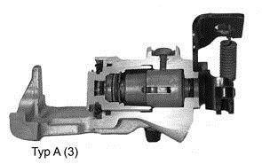
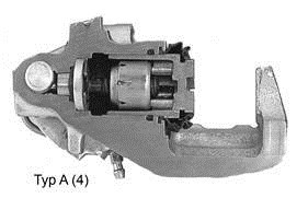
Brake calliper type A
Adjustment:
- Rotate piston, standard thread (right)
- Depending on the variant, the thread type may be left-handed or right-handed
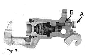
Brake calliper type B
Adjustment:
- Remove bolt A
- Adjust via hexagon screw B
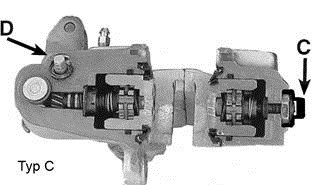
Brake calliper type C
Adjustment:
- Remove plastic cap C
- Loosen nut, adjust socket head screw, tighten nut
- Adjust hexagon screw D at the handbrake level (x = +1 mm)
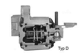
Brake calliper type D
No manual adjustment required.
Note
When performing this work, please always observe the repair instructions provided by the respective vehicle manufacturer.
Informations techniques supplémentaires
Informations techniques sur le produit
Témoin dusure de plaquette de frein
Temps de lecture: 1 minute
Informations techniques sur le produit
Indication sur le rodage des disques de frein
Temps de lecture: 2 minutes
Informations techniques sur le produit
Forte augmentation du prix du réfrigérant R134a
Temps de lecture: 3 minutes
Informations techniques sur le produit
Évaluation des dommages - Suspension et direction
Temps de lecture: 1 minute
Informations techniques sur le produit
Toyota Auris - function restriction caused by seat adjustment
Temps de lecture: 1 minute
Informations techniques sur le produit
Pièces dusure du frein de roue
Temps de lecture: 2 minutes
Informations techniques sur le produit
Pièces de rechange de freins comportant des composants en caoutchouc
Temps de lecture: 1 minute
Informations techniques sur le produit
Amortisseurs de vibration détrier de frein
Temps de lecture: 1 minute
Informations techniques sur le produit
Vérifier le voile latéral du moyeu de roue
Temps de lecture: 1 minute
Informations techniques sur le produit
Vérifier le voile latéral du disque de frein
Temps de lecture: 1 minute