Spare Parts Finder
OE-No.
Manual vehicle identification
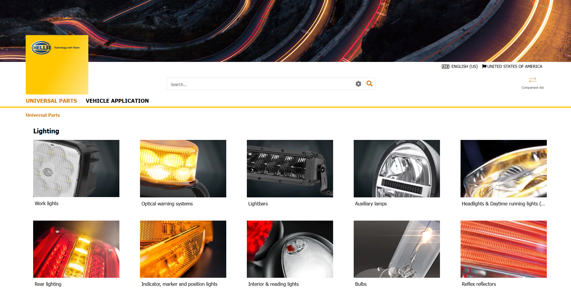
Universal Parts

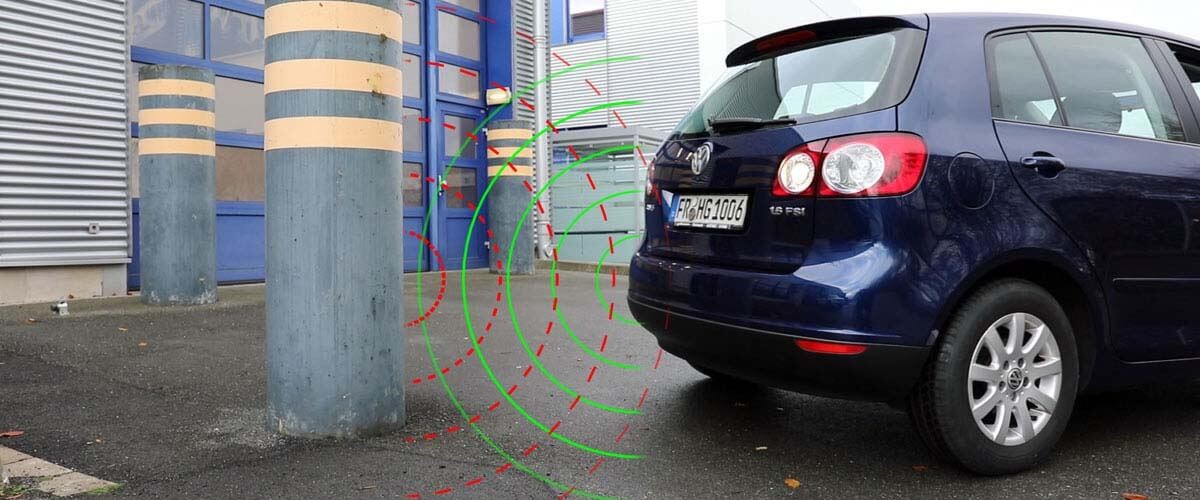
HELLA 77 GHz radar sensors are designed for use in demanding environments and offer high-resolution detection capability. They are suitable for operation in on-highway and off-highway vehicles and, depending on the sensor type, comply with protection classes including IP 6K7 and IP X9K.
Typical areas of application: