Spare Parts Finder
OE-No.
Manual vehicle identification
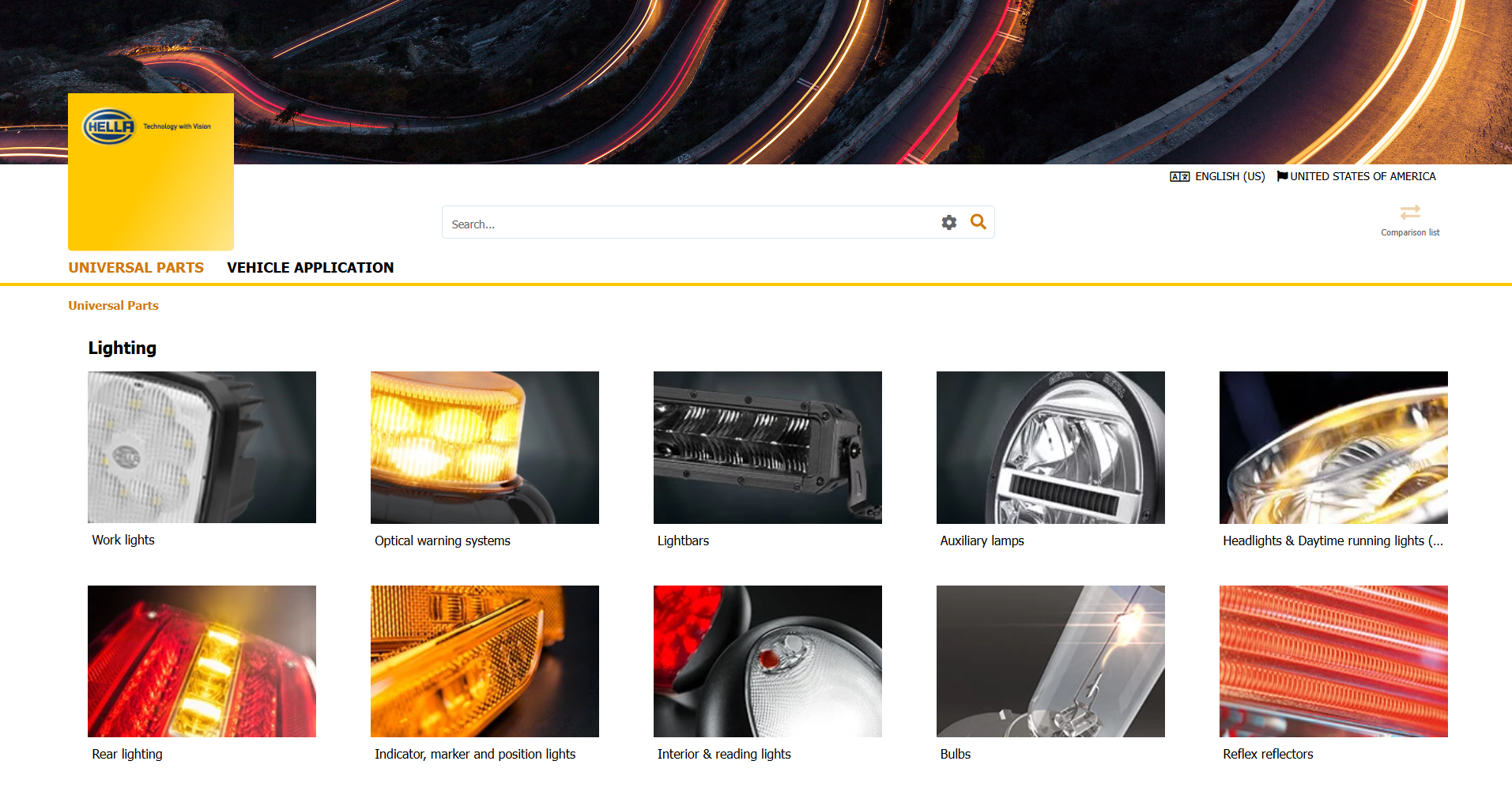
Universal Parts

Because the brake system is one of the most important systems in every vehicle, it is imperative to ensure that a constant and effective brake force is present at all times. The majority of brake boosters uses the vacuum generated by the internal combustion engine’s intake section. But under certain operating conditions, for example during the cold start and warm-up phase or when driving at extreme altitudes, the vacuum produced by the engine is no longer sufficient. In such cases, an additional vacuum pump is required in order to generate an alternative or an extra vacuum.
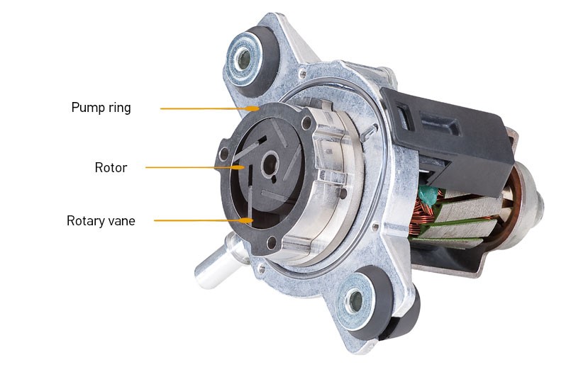
For vehicles whose engine geometry means that they have too little or no vacuum at all to operate the brake system, electric vacuum pumps are used in order to ensure the reliable operation of the brake booster. The electric vacuum pump guarantees that the reliable operation of a brake system functioning with pneumatic brake boost is maintained.
Electric vacuum pumps can be used in the following engine types:
Advantages of an additional electric vacuum pump:
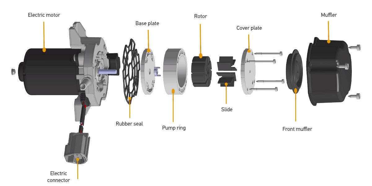
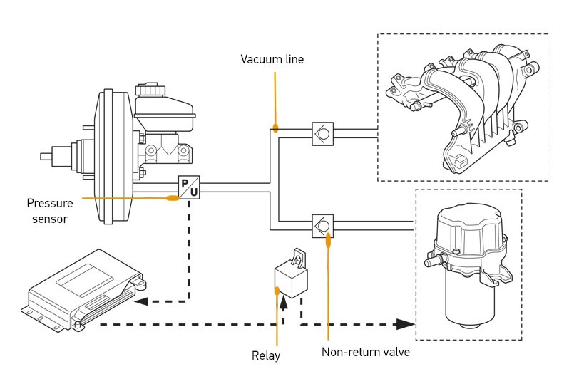
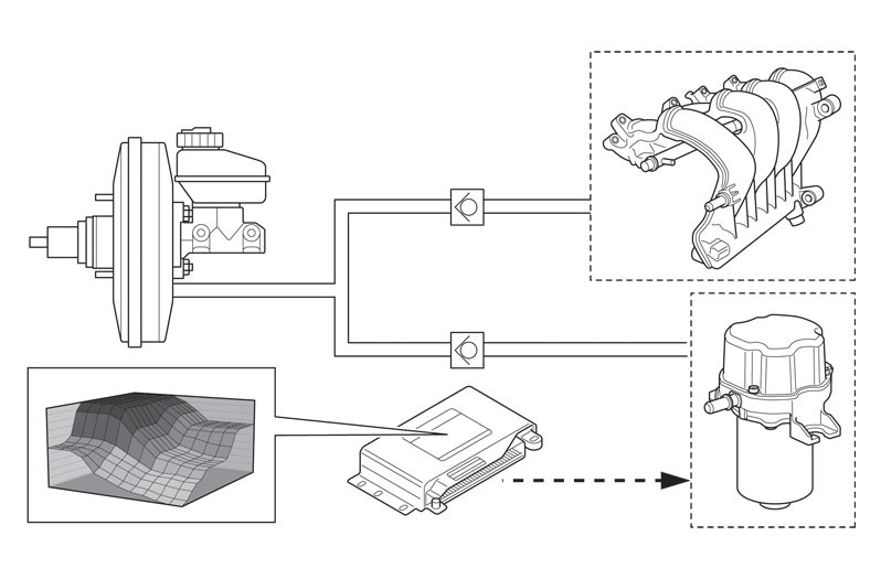
The electric vacuum pump is connected to the flexible pneumatic brake line system via a suction nozzle. The sucked-in air is filtered and moves from the passenger compartment to the vacuum pump via the brake booster and the flexible line system. The pneumatic lines, valves and the brake booster must be free of particles and all types of contamination which, if drawn in, can lead to pump damage.
Depending on the type of vehicle and on the required use, there are two kinds of vacuum pump variants which can be installed. This is where we differentiate between controlled and regulated electric vacuum pumps.
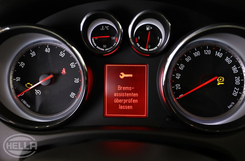
The following effects can result when failure of an electric vacuum pump occurs
The following causes can be responsible for the failure of the electric vacuum pump
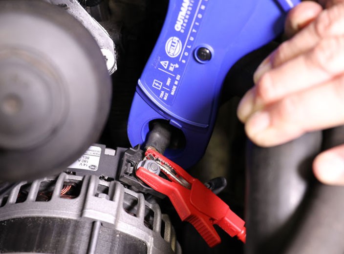
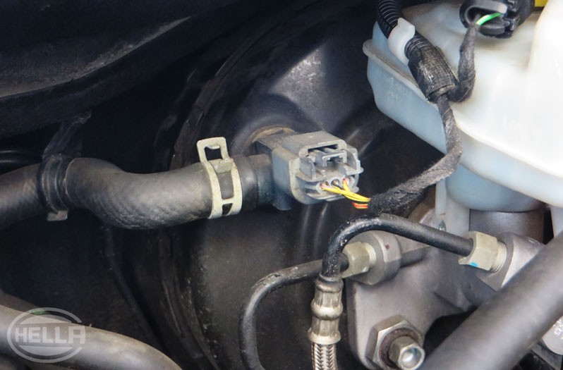
A simple functional check of the electric vacuum pump can be performed in the vehicle in the following way.
If everything in the system is in good working order, at the same time it should be possible to hear the vacuum pump temporarily running up in order to increase the required vacuum in the brake booster or alternatively balance it out.
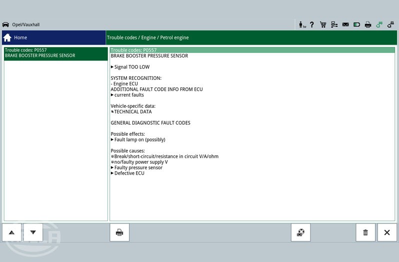
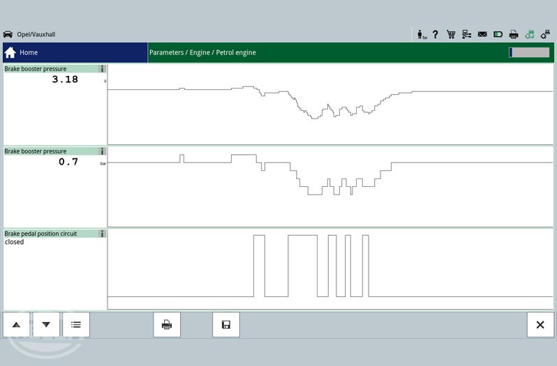
If necessary, another option would be to connect a diagnostic unit so as to show the pressure gradient in the brake booster using the "Parameter" function
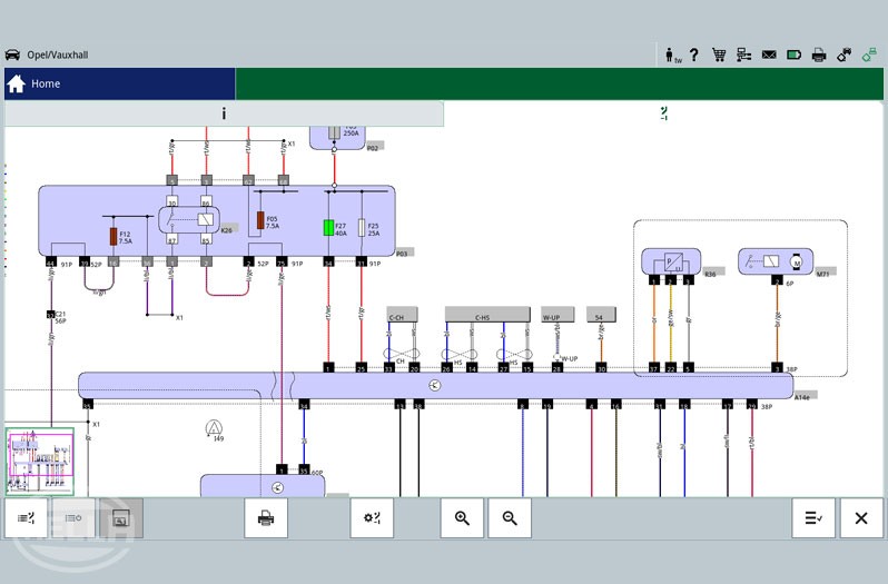
As part of control unit diagnostics, it is possible to employ the help of various functions and vehicle information as and when needed.
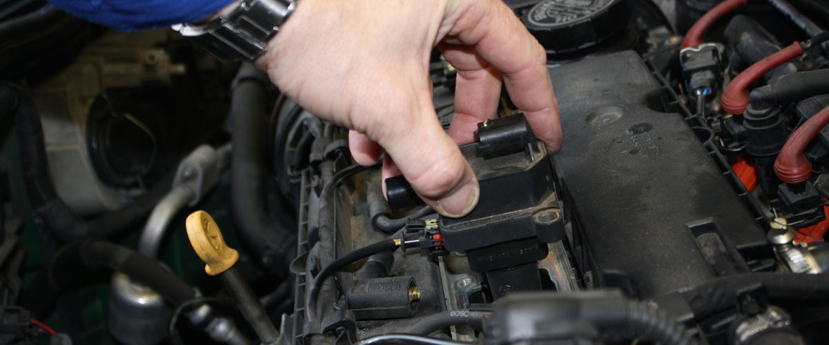
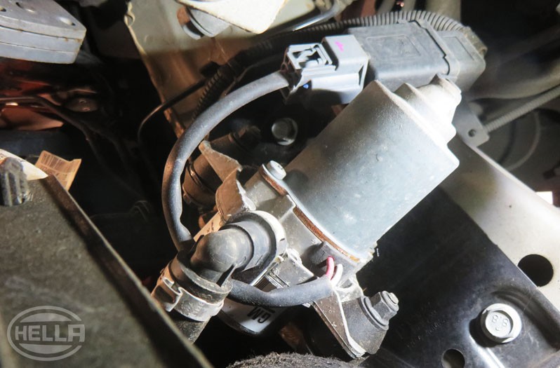
Because of the mounting position, removal of the electric vacuum pump is carried out on this vehicle model from the underside and can be completed without the need for any special tools.