Aviso de reparação, pinça de travão — Pinça móvel Teves, série FN | HELLA
Desmontar e montar o travão de discoGeralVisto que este tipo de travão de pinça controlada é instalado em muitos modelos de veículo modernos, este aviso de reparação também pode ser aplicado a outros modelos de veículo com pinças de travão do mesmo tipo.Apresentações esquemáticas, figuras e descrições têm apenas a finalidade de facilitar a compreensão e exemplificação e não podem ser utilizadas como base para a reparação.O aviso de reparação seguinte é ilustrado exemplarmente num BMW 320i (E90).Aviso de reparaçãoOs trabalhos de reparação nos sistemas de travagem só podem ser realizados por técnicos qualificados.Durante todos os trabalhos de reparação no sistema de travagem devem ser respeitados os avisos de manutenção e de segurança dos fabricantes automóveis, bem como as instruções de montagem específicas de cada produto.Trabalhos preliminaresAntes de iniciar os trabalhos de reparação, deve-se controlar todos os componentes relevantes, na zona da suspensão do eixo e do travão de roda, quanto a danos como, por exemplo, pneumáticos, tubos flexíveis dos travões ou barras transversais.Subir com o veículo para cima de um elevadorDesmontar as rodas dianteirasRealizar uma inspeção visualComponentes com defeito devem ser substituídosReparaçãoDesmontar a mola de retenção. Pressionar a mola de retenção na direção da seta, contra a tensão da mola, e retirar pela lateral Controlar a mola de retenção quanto a danos e substituir, se necessário.Atenção:A mola de retenção está sob pré-tensão.Um desencaixe repentino pela lateral pode culminar em ferimentos.Para os veículos com mais de 48 meses é recomendada a substituição da mola de retenção durante a reparação ou manutenção dos travões!Desencaixar a cablagem do indicador de desgaste dos calços de travão. Para isso deve-se abrir a caixa do conector (1) na cava da roda, destravar o conector de encaixe e desengatar a cablagem no suporte combinado (2).Aviso!No suporte combinado, na pata telescópica, são fixados de forma segura as seguintes conexões. Cabo de conexão do indicador de desgaste do calço do travão (A) Cabo de conexão do sensor ABS (B)Tubo flexível do travão da pinça de travão (C)Retirar os dois tampões de proteção dos pinos guia.Controlar os tampões de proteção e as buchas de amortecimento quanto a danos. Substituir os componentes com defeitoAviso:Infiltrações de água e sujidade podem dar origem a corrosão nos pinos guia e influenciar negativamente o funcionamento da pinça de travão.Estas podem ser a causa de um desgaste prematuro dos componentes ou de um comportamento de travagem irregular/unilateral.Desapertar e retirar os dois parafusos de fixação (pinos guia).Ferramenta necessária: chave sextavada 7 mmRetirar a pinça de travão do suporte da pinça de travão.Para isso deve-se retirar a pinça de travão para trás.Em seguida, deve-se desmontar o calço do travão interno e externo da pinça de travão.Aviso!Comparar o desgaste dos dois calços. Calços de travão com sinais de desgaste diferentes são indício para um funcionamento defeituoso da pinça de travão.Prender a pinça de travão com um gancho adequado na pata telescópica.Prestar atenção para que o tubo flexível do travão não seja torcido ou dobradoEventualmente desengatar o tubo flexível do travão no suporte, na pata telescópicaAviso:Não suspender a pinça de travão pelo tubo flexível do travão, de modo a evitar danos!Desapertar e retirar os dois parafusos de fixação do suporte da pinça de travão. Retirar o suporte da pinça de travão e controlar quanto a danos.Desmontar o disco de travão Desapertar o parafuso de fixação Retirar o disco de travãoAviso para desmontar o disco de travão.Se os discos de travão estiver preso ou encravado, deve-se bater cuidadosamente com um martelo de borracha em cima da base do cubo do disco de travão.Verificar o cubo da roda. Controlar a superfície quanto a corrosão e danos Controlar a rosca quanto a danos Rodar o cubo da roda e verificar o funcionamento síncrono e uniforme do rolamento da roda e eventuais folgasLimpar a superfície de encosto do cubo da roda com ferramentas adequadas.Remover sujidade e corrosão.Aviso:Irregularidades na superfície de encosto podem implicar a deformação do disco de travão e defeitos de excentricidade lateral!A superfície de encosto do cubo da roda não pode estar danificada, não pode ter ferrugem, tem que estar limpa e brilhante. Para prevenir a formação de corrosão deve-se pulverizar uma fina camada de óleo sobre a superfície de encosto e limpar com um pano que não desfibre.Aviso:Após a limpeza não se deve aplicar massa lubrificante em demasia a superfície do cubo da roda! A massa lubrificante pode ser projetada para cima do travão durante a rotação.A fixação da roda ou o binário de aperto dos parafusos da roda podem ser influenciados pelo problema supracitado.Montar o disco de travão e fixar com o parafuso de fixação.Aviso:Ter atenção ao binário de aperto!Preparar o suporte da pinça de travão para a montagem.Para isso aconselha-se que o suporte seja desmontado e fixado num grampo. Limpar o suporte com produto de limpeza dos travões Eliminar cuidadosamente eventual corrosão nas superfícies guia com uma escova de aço ou limaAtenção:Evitar a todo o custo danos mecânicos nas superfícies guia!Montar o suporte da pinça de travão Posicionar e apertar o parafusoTer atenção ao binário de aperto!No final da limpeza das superfícies de encosto do suporte da pinça deve-se aplicar uma fina camada de pasta para travões que não contenha ingredientes metálicos e que não tenha características de condução elétrica.Aviso!Antes de aplicar massa lubrificante, deve-se posicionar os novos calços de travão no suporte, de modo a testar a folga e o encaixe nas superfícies de encosto.Comprimir o êmbolo de travão completamente com uma ferramenta de reposicionamento.· Verificar a manga de proteção contra o pó do êmbolo quanto à fixação correta e quanto a danos.Aviso:Durante a compressão (reposicionamento) dos êmbolos deve-se observar o nível do líquido dos travões no respetivo reservatório de compensação.Eventualmente esvaziar previamente o reservatório.Limpar a pinça de travão com produto de limpeza dos travões. Aplicar uma fina camada de pasta para travões na superfície de encosto (A) do êmbolo de travão. Limpar a superfície de encosto (B) e aplicar uma fina camada de pasta para travões. Limpar a superfície de encosto (C) das cabeças de martelo/pinça de travão e aplicar uma fina camada de pasta para travões.Montar os calços de travão.Aplicar uma fina camada de lubrificante permanente sem metal nos novos calços de travão, apenas na cabeça de martelo (E), na zona da superfície de encosto (F) na pinça de travão. Posicionar o calço do travão externo no suporte da pinça Posicionar o calço do travão (do lado do êmbolo) na pinça de travão. Posicionar a pinça de travão no suporte da pinça.Aviso:Apenas é permitida a montagem de novos calços de travão, se a espessura do disco de travão for superior à espessura mínima dos discos de travão (MIN TH).Limpar os parafusos guia e controlar quanto a danos. Verificar as roscas Parafusos danificados devem ser substituídosNo final da limpeza deve-se aplicar uma fina camada de massa lubrificante nas superfícies de deslize dos parafusos guia. Nesta zona deve-se utilizar exclusivamente massa lubrificante à base de silicone.Atenção!A manga de proteção contra o pó do êmbolo de travão e ostampões de proteção e as buchas de amortecimento da guia da pinça não podem entrar em contacto com óleos ou massas lubrificantes à base de óleo mineral. Estes podem ficar danificados devido ao inchamento dos elastómeros.Desmontar a pinça de travão e fixar com os parafusos guia. Voltar a engatar o tubo flexível do travão e a cablagem do indicador de desgaste no suporte combinado Montar a mola de retençãoAvisoTer atenção ao binário de aperto!Montar um novo indicador de desgaste dos calços de travão e conectar. Prestar atenção à fixação correta do indicador de desgaste no calço do travãoVoltar a fixar a cablagem e o tubo flexível do travão no suporte combinado.Aviso:Ter em atenção que o tubo flexível do travão não seja torcido e que seja corretamente montado no suporte.Acionar repetidamente o pedal do travão até, no máx., dois terços do curso do pedal, para que os calços de travão e êmbolos de travão alcancem as respetivas posições de trabalho.Aviso:O cilindro de travão principal pode ser danificado, se premir o pedal completamente até ao fim!Verificar o nível do líquido dos travões no reservatório de compensação e eventualmente adicionar óleo até à marcação “MAX”. Se necessário, deve-se trocar o líquido dos travões.Aviso:Utilizar apenas líquido dos travões novo e autorizado para o respetivo veículo.Limpar o disco de travão após a montagem da pinça de travão O anel de fricção deve estar limpo e sem restos de lubrificante O prato do disco e as roscas devem estar limpos e sem corpos estranhos.Montar as rodas. Limpar a superfície de encosto da jante antes de montar a rodaTer atenção ao binário de aperto dos parafusos das rodas!Reposição do serviçoApós a substituição do calço do travão e do indicador de desgaste, deve-se repor o indicador Condition Based Service com um aparelho de diagnóstico adequado, segundo as especificações do cliente.Info:O sistema de manutenção CBS analisa a necessidade de serviço real no veículo. Este mede o estado das peças de desgaste e materiais de serviço mais importantes e monitoriza os serviços/necessidades de manutenção.Controlo de funcionamento e prova de estradaApós a reparação é importante realizar um controlo do funcionamento do sistema de travagem. Testar o sistema de travagem segundo as especificações e instruções do fabricante automóvel, durante uma prova de estrada. Testar o funcionamento do sistema de travagem no banco de ensaio dos travõesInformações adicionaisBinários de aperto:Veículo exemplar BMW E90/320i/N46Binários de aperto para o travão de roda no eixo dianteiro Parafuso do disco de travão no cubo da roda (16 Nm) Parafuso M 12x1,5 no suporte do travão (110 Nm) Parafuso guia da pinça de travão/Sextavado interno com abertura de chave 7 (30 Nm)Parafuso da roda (120 Nm)Outras possibilidades de teste:De modo a prevenir prematuramente vibrações durante a travagem, deve-se controlar a excentricidade lateral do novo disco de travão com um relógio comparador adequado, seguindo as instruções do fabricante automóvel.Se os valores superarem as tolerâncias, deve-se proceder ao controlo do cubo da roda e do rolamento da roda.Mais informações importantes podem ser consultadas nas Informações Técnicas:“Verificar a excentricidade lateral do disco de travão”“Verificar a excentricidade lateral do cubo da roda”Para garantir uma reparação correta aconselhamos a utilização dos seguintes produtos:Ferramentas: Comparador para disco de travão — 8PE 355 290-001 Escova para a pinça de travão — 8PE 355 290-031 Ferramenta de compressão do êmbolo do travão — 8PE 355 290-081 Lima para a pinça de travão — 8PE 355 290-091Produtos de limpeza e de lubrificação: Produto de limpeza dos travões — 8DX 355 370-001/500 ml Lubrificante permanente sem metal para travões de disco 8DX 355 370-011/75 mlLíquido dos travões — 8DF 355 360-021/1 L
General information
As this type of floating calliper brake is fitted in many modern vehicle models, these repair instructions can also be applied to other vehicle models with identical brake callipers.
Schematic representations, figures and descriptions serve only the purpose of explanation and presentation of the document texts and cannot be used as a basis for carrying out the repair.
The following repair instructions are set out using a BMW 320i (E90) as an example.
Repair instructions
Repair work on brake systems is only allowed to be carried out by qualified specialists.
The vehicle manufacturer's maintenance and safety instructions and also the product-specific installation instructions are to be observed for all repairs to the brake system.
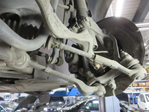
Preparatory work
Before the repair, it is advisable to check all relevant components in the area of the axle suspension and wheel brakes for damage. These would include tyres, brake hoses and wishbones.
- Drive vehicle on to a lifting platform
- Remove front wheels
- Carry out a visual inspection
- Defective parts are to be replaced
The repair
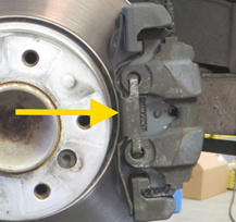
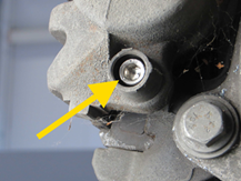
Remove the housing retaining spring.
Press the retaining spring in the direction of the arrow against the spring tension and remove it from the side
Check the retaining spring for damage and replace it if necessary.
Important:
The retaining spring is under preload.
If it jumps sideways, it could cause injury.
For vehicles older than 48 months, we recommend replacing the retaining spring as part of the brake repair!
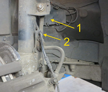
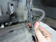
Unclip the wiring harness of the brake pad wear indicator.
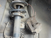
To do this, open the connector housing (1) in the wheel well, unlock the connector plug and unhook the wiring harness from the combination bracket (2).
Important!
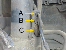
The following component connections are securely fixed in the combination bracket on the suspension strut.
Brake pad wear indicator connecting cable (A)
- ABS sensor connecting cable (B)
- Brake hose brake calliper (C)
Remove the two protective plugs from the guide bolts.
Check protective plugs and damping sleeves for damage.
Defective parts are to be replaced
Please note:
Ingress of water and dirt can lead to corrosion of the guide bolts and thus to limited function of the brake calliper.
This can be a possible cause of one-sided braking behaviour or premature wear.
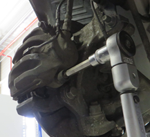
Undo and remove the two fastening screws (guide bolts).
Tools required: Allen key 7 mm
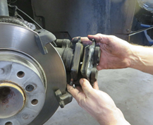
Remove the brake calliper from the brake calliper carrier.
- To do this, pull the brake calliper backwards.
- Then remove the outer and inner brake pad from the brake calliper.
Important!
Compare the wear pattern of the brake blocks. Brake pads worn differently indicate that the brake calliper is not working properly.
Tie up the brake calliper to the suspension strut using a suitable hook.
- Make sure that the brake hose is not twisted or kinked
- If necessary, unhook the brake hose from the bracket on the suspension strut
Please note:
In order to avoid damage, do not leave the brake calliper hanging from the brake hose!
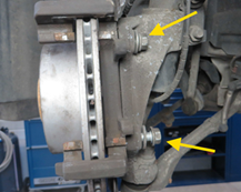
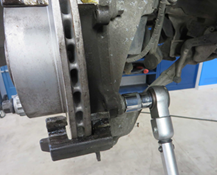
Loosen and unscrew the two fastening screws of the brake calliper carrier.
Remove the brake calliper carrier and check for damage.
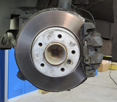
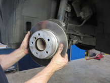
Removing the brake disc
Loosen fastening screw
Remove brake disc
Info on loosening the brake disc.
If the brake discs are stuck, carefully tap the bottom of the brake disc pot with a rubber hammer.
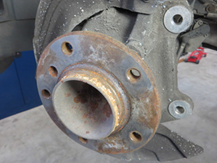
Check wheel hub.
Check the surface for corrosion and damage
Check thread for damage
Turn wheel hub and check wheel bearing for synchronisation and play
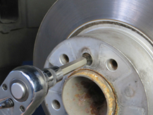
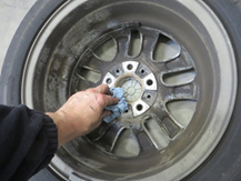
Clean the contact surface of the wheel hub with a suitable tool.
- Remove impurities and traces of corrosion.
Please note:
Unevenness on the contact surface can lead to warping of the brake disc and thus to lateral run-out!
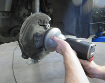
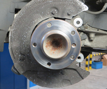
The contact surface of the wheel hub must be undamaged, rust-free, clean and metallically bright. In order to protect against corrosion, spray the contact surface with a thin layer of spray oil and wipe with a lint-free cloth.
Please note:
Do not grease the surface of the wheel hub excessively after cleaning!
Through rotation the grease can get onto the brake.
- This can affect the fastening of the wheel or the tightening torque of the wheel bolts.
Fit the brake disc and secure with the fixing screw.
Please note:
Observe the tightening torque!
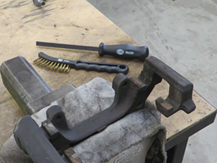
Prepare the brake calliper carrier for installation.
To do this, we recommend removing the carrier and clamping it in a vice.
Clean the carrier with brake cleaner
Carefully remove any corrosion on the guide surfaces with a wire brush or file
Important:
Mechanical damage to the guide surfaces must be avoided at all costs!
Installing the brake calliper carrier
Insert and tighten screws
Observe the tightening torque!
Then apply a thin layer of non-conductive and metal-free brake paste to the cleaned contact surfaces on the calliper carrier.
Important!
Before greasing, insert the new brake pads into the carrier as a test to check the clearance and fit on the contact surfaces.
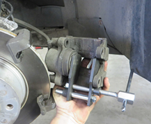
Press the brake piston all the way back with the reset tool.
Check the dust protection sleeve of the piston for a correct fit and for any damage.
Please note:
When pushing back the pistons, check the brake fluid level in the expansion tank.
If necessary, empty the tank beforehand.
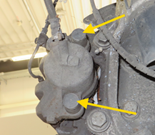
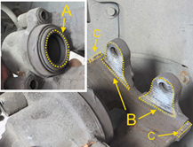
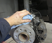
Clean the brake calliper with brake cleaner.
Apply a thin layer of brake paste to the contact surface (A) of the brake piston.
Clean the contact surface (B) and also apply a thin coat of brake paste.
Clean the contact surface (C) hammer heads / brake callipers and apply a thin coat of brake paste.
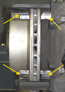
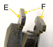
Install the brake pads.
New brake padsonly to be greased thinly with metal-free permanent lubricanton the hammer head (E), in the area of the contact surfaces (F) and on the brake calliper.
Insert the outer brake pad into the calliper carrier
Insert the piston-side pad into the brake calliper.
Place the brake calliper onto the calliper carrier.
Please note:
Only install new brake pads if the brake disc thickness is greater than the brake disc minimum thickness (MIN TH).
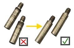
Clean the guide screws and check for damage.
Check thread
Damaged screws are to be replaced
After cleaning, apply a thin layer of grease to the sliding surfaces of the guide screws. Only use a silicone-based grease in this area.
Caution!
The dust protection sleeve of the brake piston and the
protective plugs and damping sleeves of the calliper guide must not come into contact with oils or lubricants based on mineral oil. Swelling of the elastomers can damage them.

Fit the brake calliper and secure with the guide screws.
Hook the brake hose and wear indicator cable into the combination bracket once again
Insert retaining spring
Please note
Observe the tightening torque!
Install and connect a new brake pad wear indicator.
Ensure that the wear indicator is correctly seated in the brake pad
Clip the wiring and brake hose back onto the combination bracket.
Please note:
Make sure that the brake hose is not twisted and is correctly fixed in the bracket.
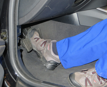
Depress the brake pedal several times with a maximum of two thirds of the pedal travel so that the brake pads and brake pistons reach their working position.
Please note:
Fully depressing the pedal can damage the master brake cylinder!
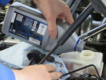
Check the brake fluid level in the expansion tank and top up to the "MAX" mark if necessary.
Change the brake fluid if necessary.
Please note:
Only use new brake fluid approved for the vehicle type.
Clean the brake disc after fitting the brake calliper
The friction ring must be free of dirt and grease
The disc pot and the threads must be clean and free of foreign bodies.
Mount the wheels.
Clean the contact surface of the rim before mounting the wheel
Please observe the tightening torque of the wheel bolts!
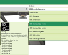
Service reset
After the brake pad and wear indicator have been replaced, the Condition Based Service display is to be reset with a suitable diagnostic device in accordance with the vehicle manufacturer's specifications.
Info:
The CBS maintenance system analyses the actual service requirements in the vehicle. It measures the condition of the most important wear parts and operating fluids and monitors the individual scopes of service.
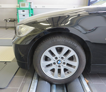
Functional test and test drive
After the repair, it is essential to carry out a functional test on the brake system.
Run in the brake system as specified by the vehicle manufacturer during a test drive.
Carry out a functional test on the brake system using a brake tester
Extra information
Tightening torques:
BMW E90/ 320i/ N46 as the example vehicle
Tightening torques for the wheel brakes on the front axle
Brake disc to wheel hub bolt (16 Nm)
M 12x1.5 bolt on the brake carrier (110 Nm)
Brake calliper guide screw / hexagon socket width across flats 7 (30 Nm)
- Wheel bolt (120 Nm)
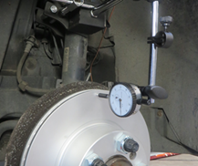
Further testing options:
In order to avoid, at an early stage, the problem of brake rubbing while driving, the lateral run-out of the new brake disc should be checked with a suitable dial gauge in accordance with the vehicle manufacturer's specifications.
If the tolerance values are not reached, the wheel hub and the wheel bearing have to be checked.
You will find further helpful content on this in the Technical Information documentation:
- “Checking the lateral run-out of the brake disc”
- “Checking the lateral run-out of the wheel hub”
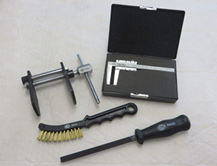
We recommend the following products for the carrying out of a safe repair:
Tools:
Brake disc calliper gauges - 8PE 355 290-001
Brake calliper brush - 8PE 355 290-031
Brake piston pressure tool - 8PE 355 290-081
Brake calliper file - 8PE 355 290-091
Cleaning agents and lubricants:
· Brake cleaner - 8DX 355 370-001 / 500 ml
Metal-free permanent lubricant for disc brakes 8DX 355 370-011 / 75 ml
- Brake fluid - 8DF 355 360-021 / 1L