Brake caliper with integrated handbrake mechanism | HELLA
Assembly note for replacement brake calipers
General installation note
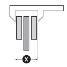
Handbrake calipers are usually set or adjusted so that the distance between the brake lining and the brake disc is at least (X) + 1 mm (fig. 1).
As vehicle manufacturers use a wide variety of different designs, they are grouped into type variants A, B, C and D within the rest of this document. Please compare the figures with the brake caliper installed in the vehicle and select the associated adjustment method.
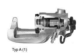
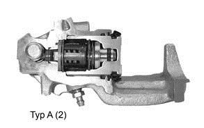
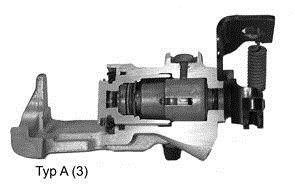
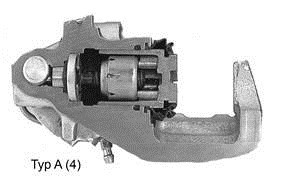
Brake caliper type A
Adjustment:
- Rotate piston, standard thread (right)
- Depending on the variant, the thread type may be left-handed or right-handed
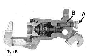
Brake caliper type B
Adjustment:
- Remove bolt A
- Adjust via hexagon screw B
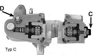
Brake caliper type C
Adjustment:
- Remove plastic cap C
- Loosen nut, adjust socket head screw, tighten nut
- Adjust hexagon screw D at the handbrake level (x = +1 mm)
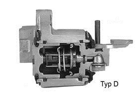
Brake caliper type D
No manual adjustment required.
Note
When performing this work, please always observe the repair instructions provided by the respective vehicle manufacturer.
Further technical information
Technical product info
Brake disks
Reading Time: 7 minutes
Technical product info
The Disc Brake Pad
Reading Time: 3 minutes
Technical product info
Repair instructions for brake calipers - removing and installing disc brakes on the Teves floating brake calipers FN series
Reading Time: 8 minutes
Technical product info
Bremsbelag-Verschleissanzeige
Reading Time: 1 minute
Technical product info
Toyota Auris - function restriction caused by seat adjustment
Reading Time: 1 minute
Technical product info
Damage assessment - wheel suspension and steering
Reading Time: 1 minute
Technical product info
Maintenance information for brake caliper Pushing the brake pistons back
Reading Time: 1 minute
Technical product info
Brake cleaner - storage information
Reading Time: 1 minute
Technical product info
Service information
Reading Time: 1 minute
Technical product info
Shear Strength
Reading Time: 1 minute