Vehicle level sensor – Design, function and troubleshooting

The vehicle level sensor is a central component for monitoring the vehicle height. The sensor measures the vertical position of the vehicle body relative to the axle or chassis. Its measurement data forms the basis for numerous vehicle systems such as the automatic headlamp levelling system, adaptive chassis systems and various stability and comfort functions.
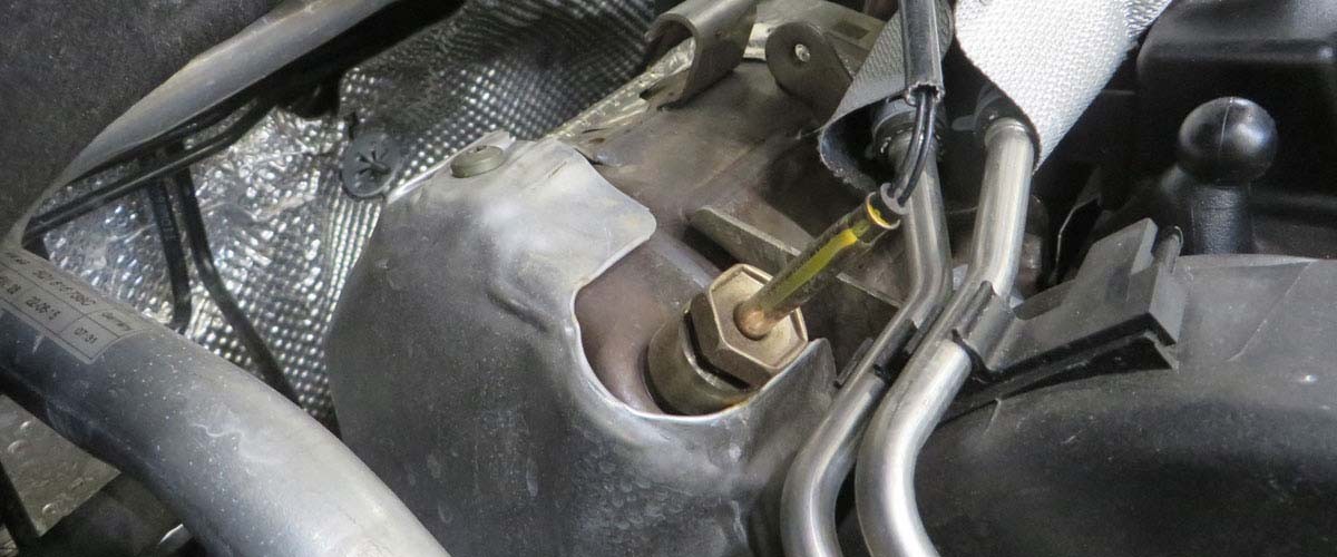
Important safety information

The following technical information and practical tips have been compiled by HELLA in order to provide professional support to vehicle workshops in their day-to-day work. The information provided on this website is intended for use by suitably qualified personnel only.

1. Design and function principle

Design and function principle of the vehicle level sensor

Vehicle level sensors are angular position sensors that are attached directly to chassis and body parts. They consist of a sensor housing that is firmly connected to the body or axle beam via a bracket, and a lever arm that is attached, for example, to the transverse control arm. The lever arm can have different lengths and methods of connection, depending on the vehicle version.

If the position between the moving chassis parts and the vehicle body or axle beam changes, the lever arm moves accordingly. It transmits this movement directly to the sensor, where it is converted into a rotary movement. The sensor converts this rotary movement into an electrical signal and sends it to the higher-level control unit. In this way, changes in ride height can be precisely detected and used to control chassis and comfort systems.

As vehicle level sensors are also used in safety-relevant systems, a particularly high level of reliability is required. That is why redundant sensors are often used. Two independent measuring channels then work in parallel. Both channels detect the same movement and each sends a signal to the higher-level control unit. If the two signal values differ from each other, the control unit detects an irregularity and can react appropriately. In this way, a possible failure is detected in good time and the functional safety of the overall system is ensured.

Sensor types frequently used in practice are:

Potentiometric sensors

This type determines the position via a variable resistor. Such sensors are often found in older vehicles or simple levelling systems. The disadvantage is the wear of the sliding contacts inside the sensor that can be worn out by the constant mechanical movement.

Inductive sensors

Inductive sensors detect movements via electromagnetic induction. The measuring principle requires no moving contacts, making the sensors robust, durable and precise. Inductive sensors are often used in systems with air suspension or in adaptive chassis.

The CIPOS® (Contactless Inductive Position Sensor) technology developed by HELLA is a special type of inductive sensor. It combines the advantages of induction with specially developed electronics and guarantees reliable operation even under the loads typically encountered in vehicles.

Typical properties:

  • Contactless and wear-free
  • Insensitive to magnetic fields
  • High temperature stability
  • Robust against vibrations, moisture and dirt
  • Multi-channel structure for redundant measurements

Inductive sensors detect movements via electromagnetic induction. The measuring principle requires no moving contacts, making the sensors robust, durable and precise. Inductive sensors are often used in systems with air suspension or in adaptive chassis.

Hall effect sensors

These sensors use a magnetic field that changes with movement. These sensors also have no moving contacts. Hall sensors are low-maintenance and reliable. Typical areas of application are modern vehicles with xenon or LED headlamps that require automatic headlamp levelling.

2. Areas of application

Areas of application

Vehicle level sensors are used in various vehicle systems:

ApplicationObjectiveSystems involved
Automatic headlamp levellingGlare-free light patternLevel sensor + headlight control unit
Air suspensionConstant ground clearanceLevel sensor + air suspension control unit
Dynamic chassis controlComfort and driving stabilityLevel sensor + damper control
Trailer operationStable vehicle level and glare-free light when loadedLevel sensor + automatic headlamp levelling or level control

Furthermore, angular position sensors can also be used in other areas, for example in agricultural vehicles or construction machinery. They are used there, for example, to detect the flap position on trailers or the bucket position on construction machinery.

3. Causes of failure

Causes of failure and symptoms

Vehicle level sensors are installed in the area of the chassis and are therefore subjected to different loads throughout the vehicle's service life. Typical causes of malfunctions or failure are:

  • Mechanical damage: Defective or bent lever arms, for example due to stones, collisions or improper installation.
  • Electrical faults: Broken cables, corrosion on plug connections or short circuits due to moisture. Internal malfunctions in the integrated circuit can also lead to faulty signals or a failure.
  • Environmental influences: Ingress of water, salt or dirt can damage the seals and the housing.
  • Wear on potentiometers: Wear of the resistor track due to continuous operation in older, mechanically operating sensors.

Possible symptoms:

  • A warning lamp lights up in the instrument cluster
  • Driver information or error messages relating to driver assistance or chassis systems
  • Fault in or failure of the automatic headlamp levelling system
  • Unusual driving behaviour with adaptive chassis (e.g. too hard or too soft)
  • Activation of an emergency running programme in the control unit
4. Diagnostics

Exemplary representation of the control unit diagnostics

The function of the vehicle level sensor is monitored by the higher-level control unit. During diagnostics, not only can the fault memory be read out but also additional functions such as parameter queries or circuit diagrams can be displayed, depending on the vehicle type. Basic settings in relation to the vehicle height may also be available, again depending on the vehicle type and configuration.

Read out the fault memory

This function allows the error codes stored in the control unit to be read out and deleted. The codes provide information on whether there are faults in the vehicle level sensor itself, in the wiring or in the communication with the control unit.

The following error code is stored in our case example:

  • Error code 49 / C103715
    • Fault detected
    • Driver information in the vehicle: Air spring: Fault! Please visit Service

Parameters

Current values of the vehicle level sensor can be displayed in this function. These include, for example, the determined height deviation from the standard position (reference height of the vehicle) or the determined vehicle height (absolute). These values are useful for being able to assess the behaviour of the sensor during operation and detecting deviations.

This allows you to check whether the signals from the left and right level sensors match or whether there are implausible values that indicate an electrical or mechanical defect.

Basic settings

After working on sensors in the chassis area or after replacing chassis components, it may be necessary to re-learn the control position. This is the reference height to which the control unit refers when controlling the chassis. The control unit adopts the current ride heights at all four wheels as target values.

The following problems may occur if the control position has not been taught correctly:

  • Incorrect vehicle height (e.g. higher or lower on one side)
  • Error messages in the instrument cluster
  • Malfunctions in the automatic levelling system
  • Impaired driving dynamics or comfort

Depending on the vehicle type and configuration, programming is carried out via the basic settings in the diagnostic unit.

Circuit diagrams

System-specific circuit diagrams can be taken from the vehicle information and used for troubleshooting. They show the electrical connection of the vehicle level sensors and their integration into the vehicle electrical system.

In this way, signal paths between the control unit and sensors can be traced and possible interruptions or malfunctions can be localised. Especially with complex chassis or lighting systems, working with circuit diagrams is an important aid to localising sources of faults quickly and reliably.

5. Repair information

Maintenance and repair instructions

  • The vehicle level sensor should only be installed and removed by trained specialists.
  • Before installation, ensure that the sensor is suitable for the intended application and that it has the required dimensions, connections and properties.
  • After installation, the chassis height should be checked using a suitable diagnostic device. Check that the control position is correctly recognised and that the sensor signals are plausible. Then delete the fault memory.
  • Depending on the vehicle type and the work carried out, it may be necessary to recalibrate the control position of the vehicle so that the current ride heights are adopted as reference values. It may also be necessary to calibrate vehicle-specific assistance systems. The ADAS CSC tool from HELLA Gutmann that can be used to precisely calibrate driver assistance systems from different manufacturers is ideal for this work.
  • The removal, installation and safety instructions of the respective vehicle manufacturer must be observed in this context.
  • HELLA accepts no liability for damage caused by improper handling or incorrect installation.
  • Country-specific regulations on occupational safety, accident prevention and disposal must be observed.

Note:

The various diagnostic options have been illustrated as examples using the mega macs X diagnostic unit. The respective test depth and variety of functions can differ from vehicle manufacturer to vehicle manufacturer and depend on the respective system configuration of the control unit. Exemplary representations, pictures and descriptions serve to explain and illustrate the document text and cannot be used as a basis for vehicle-specific repairs.

Spare Parts Finder
Manualy Oe-No. Universal Parts
Top manufacturers
Other manufacturers
Vehicle series Back
Vehicle Back

Enter the OE number in the input field. You will usually find the OE number on the spare part itself or in the vehicle documents.

Spare Parts Finder
Simple vehicle identification Also determine spare parts with OE numbers Detailed product information Find wholesalers near you
dummy
Processing Selected Car

Choose category:
Back
dummy
Teilen Sie
Send via Copy link
URL copied to the clickboard !
Article Number
Number
Article Number Was Copied !
Search The Web Mounting Instructions
More Details
Name Value
Less Details

Your Dealer
Autoteile Krammer GmbH
dummy
Lechstraße 1-3
68199 Mannheim
Show Map

How helpful is this article for you?

Not helpful at all
5
4
3
2
1
Very helpful
Success

Wrong Captcha

Wrong Captcha

Error

Something went wrong

This might also interest you

NOx-Sensor - Mercedes Benz
Basic Knowledge
NOx-Sensor - Mercedes Benz
If a fault is diagnosed in the NOx sensor when troubleshooting an exhaust gas purification system, this can present a small challenge for a workshop.
Reading time: 7 minutes
exhaust gas recirculation
Basic Knowledge
Exhaust gas recirculation – EGR valve
Everything about the exhaust gas recirculation system: causes of defective EGR valves, their inspection and replacement - knowledge for the vehicle workshop.
Reading time: 12 minutes
Check rain sensor replace
Basic Knowledge
Rain sensor & headlight sensor testing
Diagnostic and repair instructions for the rain sensor - including video instructions for removing and installing the sensor.
Reading time: 10 minutes
Service work on the loading system
Basic Knowledge
Service work on the charging system
Step-by-step instructions for servicing the charging system, including visual inspection and signal testing on the controller.
Reading time: 6 minutes
Check the starter
Basic Knowledge
Checking the starter - Causes of failure, troubleshooting
Everything you need to know about typical starter motor faults and how to rectify them - with instructions for testing and repair.
Reading time: 9 minutes
Testing alternators
Basic Knowledge
Checking the alternator
Detailed solutions for problems with the alternator - from testing to troubleshooting, everything for your vehicle workshop.
Reading time: 8 minutes
nitrogen oxide sensor nox sensor
Basic Knowledge
NOx sensor - troubleshooting and repair instructions
Everything about the NOx sensor: how it works, typical causes of failure, symptoms and fault diagnosis with the control unit.
Reading time: 8 minutes
Checking an alternator regulator
Basic Knowledge
Checking an alternator regulator
Function and design of the overrunning alternator pulley explained - including installation instructions for the overrunning alternator pulley on the alternator.
Reading time: 12 minutes
Adaptive cruise control
Basic Knowledge
Adaptive Cruise Control - adjusting sensor
How to set the ACC radar sensor correctly - with step-by-step instructions and valuable practical tips for the garage.
Reading time: 4 minutes
Keyless go
Basic Knowledge
Keyless Go & Keyless Entry system
Introduction to the Keyless Go system - from function and possible faults to diagnostics, ideal for vehicle workshops.
Reading time: 12 minutes

Great! Just one more Step

Subscription successful

Head to your inbox and confirm your email address so that you don’t miss our updates!

Get ready for brand new technical videos, car repair advice, trainings, helpful diagnostic tips, marketing campaigns and much more... delivered straight to your inbox every two weeks!