NOx sensor: Setup, troubleshooting and repair instructions

The nitrogen oxide sensor comprises a probe and a control unit. These are firmly connected together using a cable harness to form a unit. This unit is installed in the exhaust gas system and is used to recognise nitrogen oxides in the flow of exhaust gas. Nitrogen oxides are harmful to health and are produced by high temperatures, high pressure or excess oxygen during combustion in the engine. The NOx sensor is thus an important component in the exhaust gas management system of modern motor vehicles with combustion engines.

Important safety note

The following technical information and practical tips have been compiled by HELLA in order to provide professional support to vehicle workshops in their day-to-day work. The information provided on this website is intended for suitably qualified personnel only.

1. Design and Function

NOx-Sensor

The NOx sensor is installed in both petrol and diesel vehicles from Euro 5/6 and enables compliance with the strict emission values. The sensor data is required by the respective engine management systems to calculate the exhaust gas recirculation rate, the air-fuel mixture or the urea injection quantity. The sensor is necessary for vehicles with direct petrol injection, as these produce a larger quantity of nitrogen oxides due to the stratified charging operation. These vehicles also have a NOx storage catalytic converter.

In diesel vehicles, the sensor is used in conjunction with a selective catalytic reduction (SCR) system. Here, urea is introduced into the exhaust gas flow and reduces the nitrogen oxides to harmless nitrogen (N2) and water (H2O). By recording exhaust measurement data, the NOx sensor enables the engine management system to provide an optimal dosage of AdBlue®, effectively reducing nitrogen oxides, which are harmful to the environment. As soon as the required operating temperature is reached, the NOx sensor permanently measures the nitrogen oxide content in the exhaust gas. The values determined are processed by the NOx sensor's control unit and forwarded to higher-level control units, such as the SCR or engine control unit, via the CAN data bus. Based on the information received, these control units can calculate how much AdBlue® needs to be injected upstream of the SCR catalytic converter to achieve optimum nitrogen oxide reduction. A heating element integrated directly into the probe also ensures the required operating temperature of approx. 300 ° for the sensor. The NOx sensor unit can be installed individually or as a system pair in the exhaust system. This depends on which system version is installed in the respective vehicle. If two sensors are used, one is located upstream and the other downstream of the SCR catalytic converter. The downstream sensor has the task of monitoring the effect of the SCR catalytic converter. This ensures system function and more precise control of the exhaust gas purification systems. This arrangement contributes to compliance with the increasingly stringent emission limits

2. Interesting facts

Functional principle of the sensor

Exhaust gas enters the first chamber via the diffusion barrier. This houses the first pump cell and a measuring cell. The residual oxygen in the exhaust gas is determined using the measuring cell in the first chamber. Another measuring cell with a connection to the outside air serves as a reference. The difference between the oxygen content in the exhaust gas and the reference air creates a voltage between the two measuring cells, which the control unit of the sensor unit uses as a measured variable, thereby controlling the current of the first pump cell. The pump cell transports the residual oxygen out of the first measuring chamber. The remaining nitrogen oxides (NOx) pass through another diffusion barrier into chamber two, which contains a coated electrode. This electrode has the property of catalytically splitting nitrogen oxides (NOx) into nitrogen (N₂) and oxygen (O₂).
The resulting nitrogen components (N₂) diffuse outwards through a porous layer. The oxygen components (O₂) are conveyed to the outside air by the second pump cell. The control unit of the sensor unit records the pump current of the second pump cell and sends the processed information to the engine control unit via the data bus. This sensor signal is processed there and can thus monitor and control the NOx reduction.

3. Interesting facts

Integrated heating element in the NOx sensor

The integrated heating element enables a constant and optimum operating temperature to be maintained in the sensor. This allows the sensor to be heated to the predefined operating temperature regardless of the ambient temperature and engine temperature. This ensures that the NOx sensor can react optimally even at low temperatures. The temperature of the heating element is usually regulated by the engine control. The engine control unit adapts the heating output to the ambient conditions. This not only improves the accuracy of the nitrogen oxide measurement, but also has a positive effect on the service life of the sensor.

4. Important information

Causes of failure and symptoms

Due to the installation position in the exhaust system and the ambient conditions there, the functional life of the sensor is not unlimited.

A malfunction or failure can be caused by the following reasons

  • Sensor function loses efficiency
    • Wear due to ageing. Like a lambda sensor, the NOx sensor unit can also age
    • Due to operating conditions such as exhaust gas composition, temperatures and vibrations
  • Sensor head sooted
    • Short-distance operation, incorrect mixture composition or high oil consumption
  • Environmental influences
    • Moisture, water or road salt
  • Mechanical damage
    • Incorrect installation, accident or marten bite
  • Faulty power supply
    • Cable interruptions
    • External or internal short circuits
  • SCR system faulty
    • Defective components – incorrect dosing of AdBlue® can lead to deposits. These can damage the sensor and cause it to fail

The following symptoms may occur if the NOx sensor fails.

  • Engine warning light comes on
  • SCR system warning in the instrument cluster display
  • Saving an error code in the control unit
  • Malfunction or emergency operation of the SCR system
  • Increased fuel consumption or poor engine performance
5. Practical tips

Troubleshooting the NOx sensor

The function of the NOX sensor is monitored by the respective higher-level system control unit and thus via the on-board diagnostics (OBD). Component-related faults such as incorrect operational readiness, electrical short circuits or cable interruptions are recognised directly and logged in the fault memory. Therefore, the fault memory of the exhaust-relevant systems should first be read out using a suitable diagnostic device. The data from control unit communication forms the basis for actual troubleshooting and for successful repair work. However, it is recommended that the entire exhaust tract is visually inspected before starting directly with extended control unit diagnostics. External damage can usually be detected when the noise behaviour changes and can be caused by cracks or rusting through at pipes, connections or mufflers. The installed silencers and catalytic converters should also be checked for defects, such as loose parts inside, by shaking or knocking on the respective component. Wiring or electrical plug connections may have been damaged here due to environmental influences such as dirt, water or road salt. The electrical plug connection on the control unit should thus also be included in the troubleshooting process. If no damage is detected, the power supply and data bus communication should be checked using a suitable measuring device in accordance with the manufacturer's specifications.

6. Instructions

Example of the control unit diagnostics

Depending on the vehicle and system, the fault memory can be read out and additional functions such as parameters or circuit diagrams can be selected and displayed. The following information was provided using a BMW 520D G31 as an example.

1

Reading out the engine control system’s error memory

In this function, the error codes stored in the engine control can be read out and deleted.

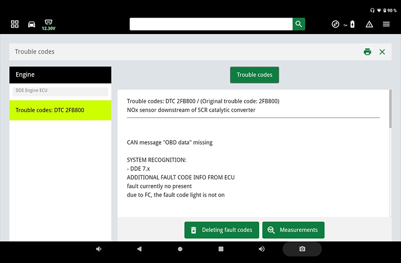
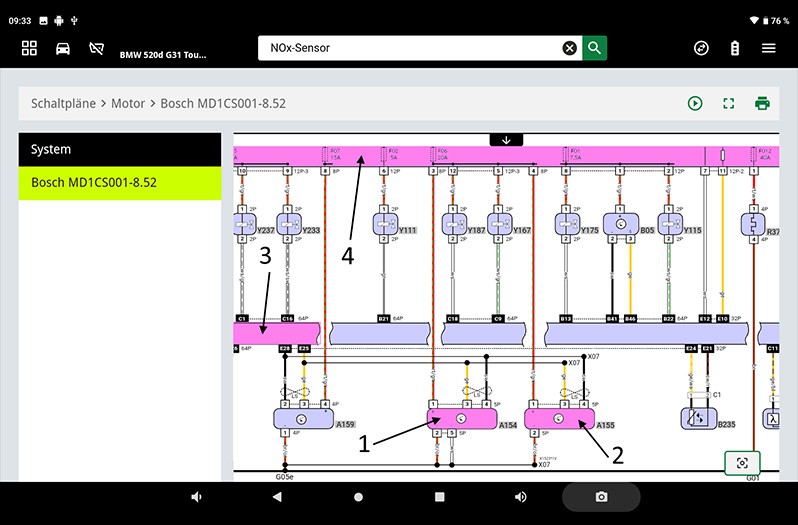
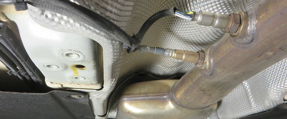
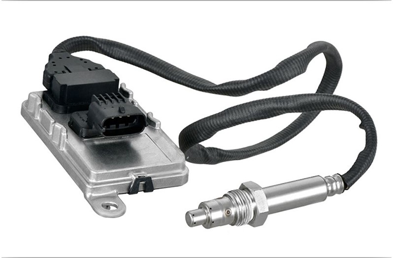
In our case study, an error relating to the NOx sensor downstream of the SCR catalytic converter was stored in the error memory.

  • Error code 2FB 800 "OBD CAN message missing"
    • Error present
    • Error lamp not switched on

2

Reading off parameters

This function can be used to display current measured values such as engine speed, NOx value before and after SCR catalytic converter, as well as the temperature of the SCR catalytic converter.

This parameter query can be used during operation to check whether the exhaust gas sensors and the SCR system are functioning properly.

As can be seen in our example, no value is displayed for the faulty NOx sensor after SCR catalytic converter

3

Basic adjustment

After installing the NOx sensor with control unit, this vehicle must be adapted to the vehicle.
In this function, the stop values of the new turbocharger unit can be programmed into the higher-level control unit.

4

Circuit diagrams

System-specific circuit diagrams can be taken from vehicle information and used for troubleshooting purposes. Here, for example, the PIN assignment on the NOx sensor can be read and used for further troubleshooting.

7. Workshop tips

Maintenance and repair instructions

  • Installation should only be carried out by trained, qualified personnel.
  • As part of the troubleshooting process, a visual inspection of the components and peripherals in the engine compartment or on the exhaust system should first be carried out after the control unit diagnosis.
  • The NOx sensor should be replaced if the wiring or sensor housing is damaged.
  • The sensor should always be replaced as a complete unit in the event of repair.
  • Ensure the correct sensor and installation position! Do not mix up the position before and after the catalyser.
  • The thread of the NOx sensor must not be additionally coated with hot screw paste.
  • NOx sensors must be tightened with the specified tightening torque!
    We recommend a tightening torque of 50 Nm for HELLA NOx sensors.
  • Before installation, it is important to ensure that the product is suitable for the intended application and that it has the required dimensions, connections and properties or features.
  • After installation of the NOx sensor with control unit, it may also be necessary to adjust it to the vehicle by using a suitable diagnostic device!
  • Please always observe the relevant installation and removal instructions provided by the vehicle manufacturer!
  • HELLA accepts no liability for damage caused by the improper handling or incorrect installation of the product!

Important

The various diagnostic options have been illustrated as an example using the mega macs X diagnostic device. The respective test depth and variety of functions can be set out differently depending on the vehicle manufacturer and these are dependent on the relevant system configuration of the control unit. Schematic illustrations, pictures and descriptions serve to explain and illustrate the document text and cannot be used as a basis for vehicle-specific repairs.

8. FAQ – Frequently Asked Questions

FAQ – Frequently Asked Questions

Why is the NOx sensor always made up of a probe and a control unit as a single unit?

The NOx sensor requires its own signal processing, since measurements are based on pump flow rates and internal control loops. These signals are not directly comparable to conventional, analogue inputs. The integrated control unit processes raw data according to temperature and system parameters, and only then provides CAN-compatible measurement values for the engine or SCR control unit.

How can an NOx sensor appear to be operating normally, yet still generate incorrect readings?

Sensor element ageing alters the electrochemical properties of the measurement and pump cells. In this process, power supply and bus communication often continue to operate perfectly. However, the control unit increasingly detects implausible NOx values or control deviations that are only identified by comparing parameters or monitoring the SCR system's efficiency.

What's the integrated heating element's role in diagnosing NOx sensors?

The sensor only operates reliably once it has reached a defined operating temperature. The heating element safeguards this regardless of the exhaust gas temperature. Faults in the heating control system may result in delays in being ready for measurements, unstable NOx readings or missing signals. Such faults are often categorised as malfunctions rather than mere heating faults.

Why do NOx sensor faults occur more frequently after having only driven a short distance?

If the vehicle is mainly used to cover short distances, the sensor only briefly or insufficiently reaches its operating temperature. Condensate, fuel or oil particles in the exhaust gas may cause deposits on the sensor element. This accelerates ageing and may lead to a delayed response or incorrect NOx readings.

How can you tell the difference between an electrical fault in the NOx sensor and a functional measurement error?

Electrical faults usually manifest themselves as missing or constant measured values, communication failures or CAN-related error codes. Functional measurement errors, on the other hand, result in implausible, yet fluctuating NOx values. In many cases, these still remain within the electrical limits, but lead to control deviations in the SCR system or to faulty AdBlue metering strategies.

How does incorrect AdBlue metering impact the NOx sensor's lifetime?

Overdosing or underdosing causes deposits or chemical loads in the exhaust system. Crystallised residue or ammonia slip may damage the sensor element. The NOx sensor responds to this by generating a delayed signal or failing completely, even though there is no electrical fault.

Why does a new NOx sensor often require teach-in or initialisation?

The superordinate control unit stores sensor and system-specific teach-in values. After replacement, these must be reset so the new sensor element is correctly integrated into the control loop. Without the basic settings, error messages or restricted SCR function may still be output even if the sensor is operating properly.

Why is the correct tightening torque of NOx sensors technically relevant?

Insufficient torque may lead to exhaust gas leaks and falsified measurement conditions. Excessive torque may damage the sensor housing or ceramic structure. Both factors have a direct impact on measurement accuracy as well as service life and may lead to sporadic or permanent measurement errors.

Why is it advisable to carry out a visual inspection and check the exhaust system before diagnosing a sensor?

Leaks, cracks or loose components in the exhaust system locally alter the exhaust gas composition. The NOx sensor then generates inaccurate readings, even though it is technically in good working order. Without a prior mechanical inspection, there is a risk of incorrect diagnosis and replacing the sensor unnecessarily.

What are typical diagnostic errors when testing NOx sensors in the workshop?

The sole focus is frequently on the sensor without taking into account the wider system context. Unchecked power supplies, CAN communication, exhaust leaks or faulty SCR components cause recurring faults. Merely analysing the NOx sensor is not enough when troubleshooting.

How helpful is this article for you?

Not helpful at all
5
4
3
2
1
Very helpful
Success

Wrong Captcha

Wrong Captcha

Error

Something went wrong

Spare Parts Finder
OE-No. Manual vehicle identification
Top manufacturers
Other manufacturers
Vehicle series Back
Vehicle Back

Enter the OE number in the input field. You will usually find the OE number on the spare part itself or in the vehicle documents.

Spare Parts Finder
Simple vehicle identification Also determine spare parts with OE numbers Detailed product information
dummy
Processing Selected Car
Manufacturer
Vehicle series
Vehicle
Engine output
Engine displacement
Fuel type
Construction year
Engine code

Choose category:
Back
dummy
Share
Send via Copy link
URL copied to the clickboard !
Article NUmber
Number
Article Number Was Copied !
Search The Web Mounting Instructions
More Details
Name Value
Less Details

Your Dealer
Autoteile Krammer GmbH
dummy
Lechstraße 1-3
68199 Mannheim
Show Map

You might also be interested in

A vehicle with an active ADAS system recognises pedestrians and e-scooters in urban traffic by means of radar and sensor signals – a good example of autonomous driving and sensor fusion.
Basic Knowledge
Title ADAS und autonomes Fahren: Überblick für Werkstätten
Alles über ADAS und autonomes Fahren: Funktionen, Sensorfusion, KI und Diagnosegeräte – kompakt erklärt für Kfz-Profis
Reading Time: 14 minutes
NOx sensor - Mercedes Benz
Basic Knowledge
NOx-Sensor - Mercedes Benz
Wird im Rahmen einer Fehlersuche an einem Abgasreinigungssystem ein Mangel am NOx-Sensor diagnostiziert, kann dies für eine Werkstatt eine kleine Herausforderung darstellen.
Reading Time: 7 minutes
HELLA 77 GHz radar sensors: Design, function and applications
Basic Knowledge
Wartung und Diagnose von 77-GHz-Radarsensoren
Erfahren Sie, wie der HELLA 77-GHz-Radarsensor Fahrerassistenzsysteme unterstützt und Objekte bei jeder Witterung präzise erkennt. Entdecken Sie Aufbau, Funktion und Anwendungen im Fahrzeug.
Reading Time: 7 minutes
Basic Knowledge
E-Mobilität im Werkstattalltag: Technik und Anforderungen
Elektromobilität verändert die Werkstattpraxis: Erfahre, wie Werkstätten mit Hochvoltsystemen, neuen Diagnoseverfahren und gezielter Qualifikation arbeiten
Reading Time: 16 minutes
Replacing the horn
Basic Knowledge
Replacing the horn - Instructions
Step-by-step instructions for replacing the horn on various models such as the Audi TT/RS and Grand Cherokee.
Reading Time: 5 minutes
Check multifunction controller
Basic Knowledge
Checking the alternator regulator
Find out how to check the multifunction regulator, measure the generator voltage and ensure that the regulator is functioning correctly.
Reading Time: 4 minutes
Starter damage assessment
Basic Knowledge
Starter damage assessment
Starter faulty? Spot typical causes such as overloading or misfiring and find out how to repair damage effectively.
Reading Time: 1 minute
Starter damage assessment
Basic Knowledge
Alternator damage assessment
How to diagnose damage to the alternator: ranging from corrosion and short circuits right up to bearing damage.
Reading Time: 1 minute
Ignition coil
Basic Knowledge
Ignition coil – checking, measuring, faults
Recognize symptoms of a defective ignition coil and get to know ignition coil types - with instructions for troubleshooting and testing.
Reading Time: 14 minutes
Ultrasound-based parking aid - park distance control (PDC)
Basic Knowledge
Park Distance Control (PDC): a parking aid based on ultrasound
Learn all about the function and maintenance of ultrasonic parking aids (PDC), including repair tips.
Reading Time: 5 minutes

Quick question

Great! Just one more Step

Subscription successful

Head to your inbox and confirm your email address so that you don’t miss our updates!

Get ready for brand new technical videos, car repair advice, trainings, helpful diagnostic tips, marketing campaigns and much more... delivered straight to your inbox every two weeks!