Brake disks | HELLA PAGID
General information
Since the introduction of the disk braking system to the automobile, it has become a key structural component in automotive engineering.
Together with the brake lining, the brake disk forms a friction couple which is subject to wear and tear and must be able to withstand extreme forces.
Both components ensure production of the braking torque required to decelerate or brake a vehicle to a standstill. The brake disk transfers this braking torque to the wheel hub and from there to the rim.
It is also responsible for dissipating the thermal loads acting on the wheel brake.
Material
Brake disks are exposed to heavy mechanical loads under braking. In addition to compressive forces, tensile forces and centrifugal forces, they must also withstand thermal loads. In order to achieve the best possible results in every braking situation, the material compositions of the brake disk and brake lining must be ideally compatible. Depending on the vehicle type and the application, brake disks can be made of grey cast iron, stainless steel, carbon or ceramic materials. The majority are made of grey cast iron, whose properties are improved by adding a wide range of materials. Admixing molybdenum and chromium improves the heat crack properties and the abrasion resistance of the alloy. Thermal absorption is improved by increasing the carbon content.
For cost reasons, brake disks made of ceramic materials or carbon are used in motor sport or high-value vehicle classes. Alongside low weight, a long lifetime and excellent response, their excellent anti-fading properties are a further benefit.
These brake disks, however, require special brake linings to compensate for their poorer thermal conductivity.
Designs
When braking, friction causes the kinetic energy to be converted into heat energy. Up to 90% of this converted energy is absorbed by the brake disk and released to the ambient air.
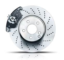
As a result, in extreme conditions temperatures of up to 700°C can occur on the wheel brakes. In addition to the physical loads, brake disks are also exposed to environmental influences, dirt, water and salt. All these factors must be accounted for in the design at the brake disk manufacturer and necessitate a range of brake disk types. A general distinction here is made between solid and ventilated brake disks (fig. 1).
A solid brake disk is integrally cast and has just one friction ring. Because solid brake disks can only dissipate heat slowly, they are typically installed in the compact car class. In heavy or high-performance vehicles, they are primarily used on the rear axle which is exposed to a lower brake power load. Due to better brake control, they sometimes replace the drum brake there.
With their greater mass, ventilated brake disks have a better heat storage capacity and cool down faster due to their radial air ducts (fig. 2). These ducts are located between the two friction rings. The rotation of the brake disk causes a fanning action which produces a constant air current through the brake disk.
Because dynamic axle load distribution means that greater braking forces act on the front axle, ventilated brake disks are usually installed on the front axle. This ensures excellent brake power under extreme conditions. Depending on the vehicle type, application and engine power, ventilated brake disks can be installed on both the front and rear axles.
In addition, solid and ventilated brake disks may feature slits and grooves or be axially perforated. Brake abrasion, water and dirt collect in the slits or grooves and are discharged outward by the rotational movement. The axial holes increase heat dissipation but have no self-cleaning effect, because brake abrasion may be deposited in them.
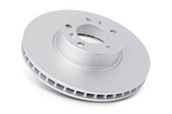
Fig. 1
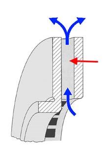
Fig. 2
Variants
Depending on the vehicle or brake system design, brake disks installed on the rear axle of a vehicle may also feature an integrated brake drum for the handbrake mechanism in the brake disk chamber.
Some manufacturers also integrate wheel bearing and pulse rings for the antilock system (fig. 3) in their brake disks. Both designs demand a high degree of care by technicians when performing repairs. Brake disks are partly coated to improve their corrosion resistance. These brake disks can be coated with an anti-rust finish completely or outside the friction ring. At the same time, the visual effect is improved in the exposed rim area of the wheel brake. If the brake disk is completely coated, a moderate running-in period is recommended until the brake lining and the disk have adapted to one other and the paint coat on the friction ring has detached due to friction.
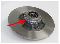
Fig. 3
Brake judder
This is a low-frequency vibration in the vehicle caused by braking.
A distinction is made between cold and hot judder.
Cold judder is apparent in the form of steering wheel jitter, fluctuations in braking force or a pulsating brake pedal. It is caused by a difference in thickness in the brake disk, which is attributable to uneven wear and presents when the brake is released. The friction ring erosion caused by static wheel imbalance induces periodic contact of the brake disk and the brake lining during rotation. Hot judder is caused by reversible brake disk deformation associated with uneven warming of the brake disk. Overheating can cause the brake disk friction ring to deform excessively outward or inward. This is further exacerbated by local heat zones (fig. 4) on the brake disk. The cause may be an undersized brake disk, worn brake lining or the use of brake products which do not comply with manufacturer specifications.
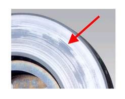
Fig. 4
Wear and testing
Brake disks are subject to natural wear and tear due to high mechanical and thermal loads and additional environmental impact. The state of the brake system should therefore be regularly checked at the servicing intervals recommended by the manufacturer. The wear limit of the brake disk is set by the manufacturer as a minimum thickness of the friction ring. This value, in millimetres, is stated or stamped on the rim (fig. 5) of the brake disk. The value is calculated so that on reaching this thickness, under normal driving conditions and taking into account the previous brake lining service intervals, another set of brake linings can be installed. If the garage does not have any information on this, it is advisable to replace the brake disks and linings.
Additional tests include concentricity (lateral runout), and thickness difference (differing disk thicknesses) in the brake disk.
The concentricity test for brake disks is performed with disks installed (fig. 6). A dial gauge placed approx. 10 to 15 mm below the outer disk radius is used to perform the measurement. Measured over several wheel revolutions, deviations should not exceed 0.070 mm for new vehicles and 0.10 mm for older vehicles, due to greater tolerances. This test is only meaningful for new brake disks. If deviations are found, the state of the wheel hub and bearing should be considered as further fault sources.
The measurement of thickness difference in the friction ring of a brake disk can only be precisely carried out with special equipment. A micrometre calliper, however, also provides sufficient measuring accuracy of ± 0.001 mm. Measurement should be carried out at 12 to 15 positions on the circumference of the disk and approx. 10 to 15 mm below the outer friction radius. Depending on the vehicle type, thickness differences of 0.012 mm to 0.015 mm can already cause judder phenomena. As a result, these values must not be undercut on new brake disks.
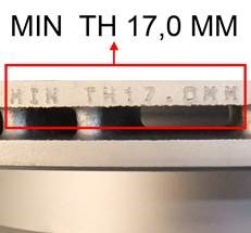
Fig. 5
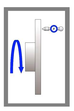
Fig. 6
Maintenance information
In order to ensure perfect functioning, the following points are recommended:
- Brake disks should always be replaced in pairs
- Always install new brake disks with new brake linings
- The supporting surface of the wheel hub should be flat, burr-free, clean, rust-free and without damage
- As required, observe the running direction for ventilated brake disks
- Completely remove corrosion protection with suitable cleaning agents
- Observe the specified torque
- Because brake disks and brake linings must adapt to one other, comply with a moderate running-in period for the brake system Observe manufacturer information
- Avoid unnecessary sudden braking in the first 100 km
- Observe the product’s instruction leaflet
- Observe the vehicle manufacturer’s installation instructions
- Repairs to the brake system should only be carried out by trained personnel
Important safety note
Technical information and practical tips have been compiled by HELLA in order to provide professional support to vehicle workshops in their day-to-day work. The information provided on this website is intended for use by suitably qualified personnel only.
Reprinting, distribution, reproduction, exploitation in any form or disclosure of the contents of this document, even in part, is prohibited without our express, written approval and indication of the source. The schematic illustrations, pictures and descriptions serve only for the purposes of explanation and representation of the instructions and cannot be used as a basis for installation or assembly work. All rights reserved.
Not helpful at all
Very helpful