Car airbag system

Here you will find useful information and important tips relating to the airbag system in vehicles.

Passive safety systems are responsible for ensuring that passengers are protected to the greatest possible extent in the event of an accident. A wide variety of airbags are available nowadays, and they are now provided as standard in all vehicle classes. This page explains which components can be found in a modern restraint system and how airbags and seat belt tensioners protect drivers against injury in an emergency. You will also find important information on troubleshooting passive safety systems.

Important safety note The following technical information and practical tips have been compiled by HELLA in order to provide professional support to vehicle workshops in their work. The information provided on this website is intended for use by suitably qualified personnel only.


CAR AIRBAG SYSTEM SRS: BASIC PRINCIPLES

This section focuses on the airbag system. We will explain the individual components, what they do, how airbags are deployed, and steps you can take when troubleshooting. Recent years have seen rapid advancements in airbag technology since airbag systems were first introduced. As such, we will only describe the components and processes in general terms.


If you would like more detailed data on the systems installed in specific vehicles, always consult the vehicle manufacturer's specifications. Maintenance and diagnostics must only be performed by appropriately trained professionals.


Ensure that all legal principles and guidelines are complied with when carrying out this work. The initial idea for an airbag system can be traced back to the 1960s. At that time, a major obstacle was the time available for the airbag to inflate. Attempts were made to solve the problem using compressed air, but this solution was unsuccessful. The first successes were recorded at the start of the 1970s with the use of pyrotechnic propellant charges to inflate the airbag in the specified time.


The first airbag systems were installed in top-of-the-range vehicles in the mid-1970s and at the start of the 1980s. The end of the 1980s saw the introduction of the front passenger airbag, and this was gradually followed by other variants such as the head airbag and side airbag. Nowadays, airbag systems are provided as standard in vehicles.

AIRBAG FUNCTION: COMPONENTS

Airbag control unit

The control unit is the heart of the airbag system and is installed centrally in the vehicle. It can generally be found in the dashboard area, on the centre tunnel.


It is responsible for the following:

  • Detecting accidents.
  • Detecting the signals sent by the sensors in a timely manner.
  • Triggering the necessary firing circuits in a timely manner.
  • Providing the power supply to the firing circuits using the capacitor, independently of the vehicle battery.
  • Running self-diagnostics on the entire system.
  • Storing faults in the fault memory.
  • Activating the airbag indicator lamp if the system fails.
  • Connecting to other control units via the CAN bus.

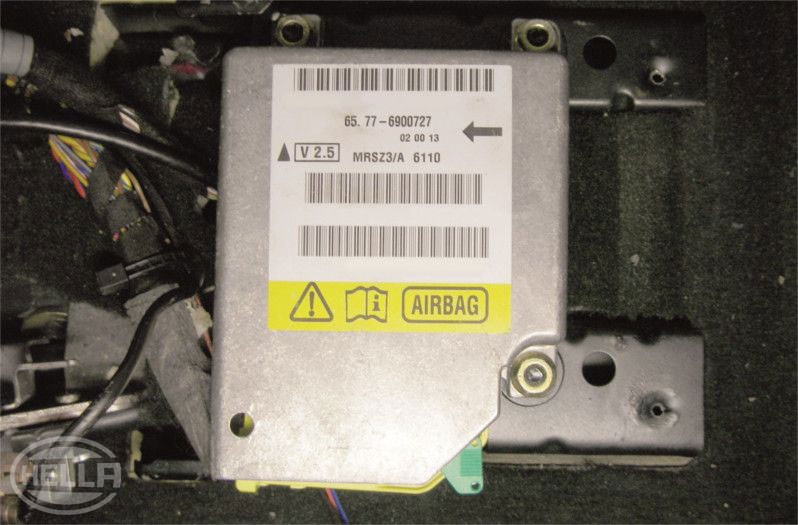
Information acquired from a range of crash tests is saved in modern control units. This information enables an accident to be classified according to the "crash severity".


In this context, a distinction is made between the following:

  • Crash severity 0 = minor accident; no airbags are deployed
  • Crash severity 1 = moderate accident; airbags may be deployed in the first stage
  • Crash severity 2 = serious accident; airbags are deployed in the first stage
  • Crash severity 3 = very serious accident; airbags are deployed in the first and second stages


Alongside the crash severity, the control unit also takes into account information about the direction of the accident (the application of force), for example 0° or 30°, and the type of accident in order to determine the deployment strategy. In addition, it considers whether or not the occupants are wearing their seat belts.

Crash sensors

Depending on the airbag system and the number of airbags installed, the crash or acceleration sensors are installed either directly in the control unit or as satellites in the vehicle front end or at the side of the vehicle.


Front sensors are always provided in duplicate. These sensors usually operate according to the spring-mass system. With this system, the sensor houses a weighted roller which is filled with standardised weights. A bronze spring hinge is wound around the weighted roller and its ends are attached to the weighted roller and the sensor housing. As a result, the weighted roller can only move if the force is applied from a certain direction. If force is applied, the weighted roller rolls against the bronze spring force and closes the circuit to the control unit using a contact. The sensor also houses a high-impedance resistor in order to run self-diagnostics.

Another expansion option for movement sensors is to use a silicon mass. If force is applied, the silicon mass in the sensor moves. Due to the way in which the mass is suspended in the sensor, this changes the electrical capacitance, which serves as information for the control unit.


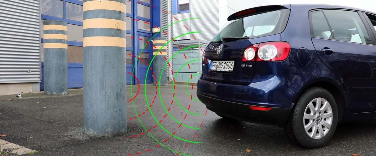
Thanks to the speed at which they can record information, these sensors are used to supply information to the control unit as quickly as possible in the event of a side impact.


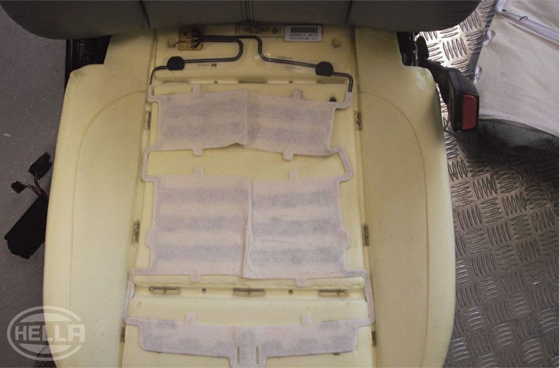
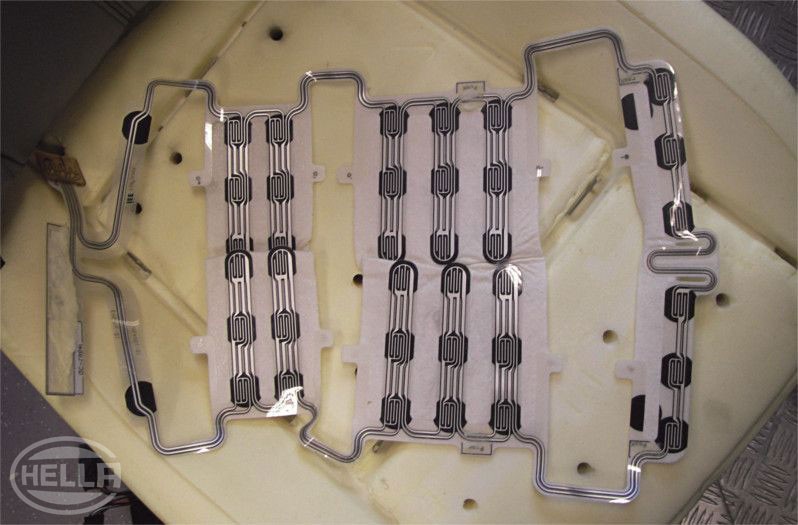
Pressure sensors are also used. They are installed in the doors and respond to changes in pressure inside the doors in the event of an accident. When working on vehicles that use these pressure sensors, it is essential to properly refit the door sealing foils following their removal. If the door sealing foil has been incorrectly fitted and this results in pressure loss during an accident, the function of the pressure sensors may be impaired.


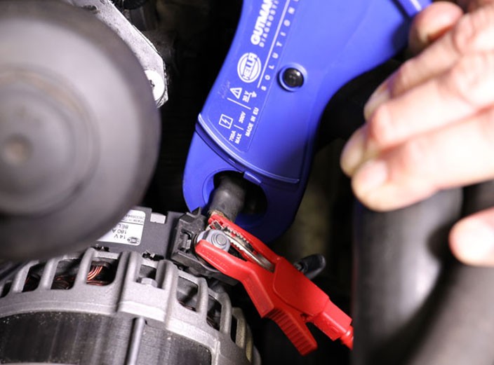
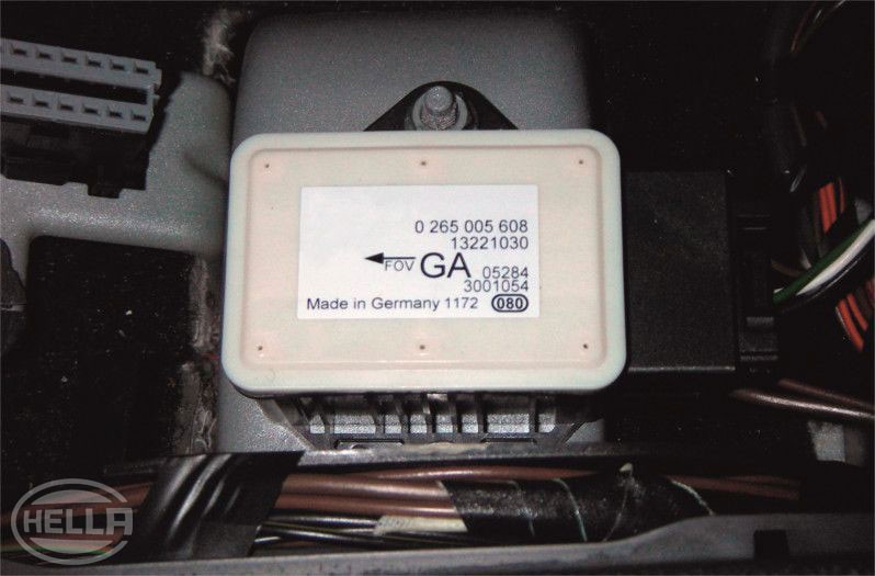
When mounting the crash sensors, always observe the installation direction, which is indicated by an arrow on the sensor. The deployment threshold is an acceleration of approx. 3 – 5 g. For safety reasons, in order to avoid the airbag(s) being deployed unintentionally, two sensors that operate independently from one another must always send the information to deploy the airbag(s). The safing sensor is used as a safety sensor.

Safing safety sensor

The safing sensor is responsible for preventing the airbags being deployed unintentionally.


It is series-connected with the front sensors. The safing sensor is integrated into the airbag control unit. It comprises a reed contact in a resin-filled tube and a ring-shaped magnet. The open reed contact is located in a resin-filled tube over which the ring-shaped magnet is placed. The magnet is held by a spring at the end of the housing. If force is applied, the magnet slides over the resin-filled tube against the spring force and closes the reed contact. This closes the contact for firing the airbags.

AIRBAG DESIGN: DESIGN

The steering wheel airbag comprises an airbag with a volume of approx. 67 l, the airbag holder, the generator on the generator support, and the airbag cover (steering wheel cover). In the event of an accident, the control unit fires the generator. In the process, a trigger current heats up a thin wire that fires the firing pellet.


As the process continues there is no explosion – instead, the propellant is burned. This propellant is made from sodium azide. The gas produced while the propellant burns expands and reacts with the oxidizer (a substance which releases oxygen, such as copper oxide or iron oxide) to form almost pure nitrogen which fills the airbag. Due to the toxicity of sodium azide, other azide-free solid fuels are also used as propellant. These don't just form nitrogen when they react, but also carbon dioxide (approx. 20%) and water vapor (approx. 25%). The propellant is usually provided in the form of tablets, packed air-tight in the combustion chamber.

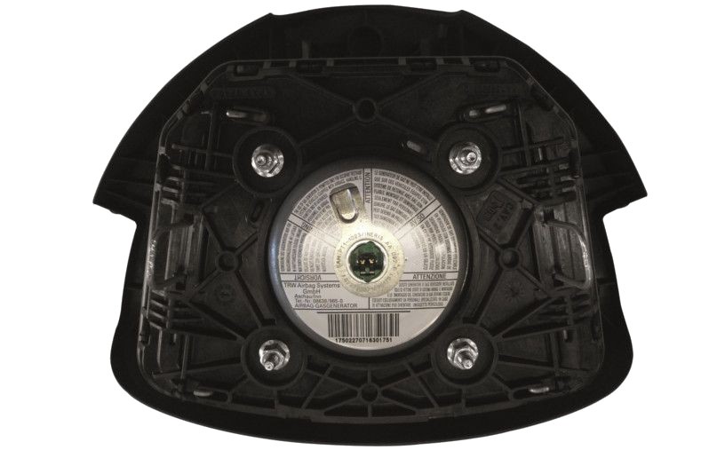
Which propellant is used depends on the size of the airbag and the required opening speed. The chemical reaction that takes place following the firing causes temperatures of 700°C in the combustion chamber. The resulting gas flows through a filter screen at a pressure of approx. 120 bar. In the process, it is cooled down to reduce the temperature at the outlet to less than 80°C in order to protect the occupants. The noise produced is similar to a gunshot. It takes around 30 ms for the airbag to fully inflate. Newer systems use two-stage gas generators. Depending on the severity of the accident, the control unit fires the two firing pellets one after the other. The shorter the interval between the firings, the faster the airbag will inflate. In any case, both gas generators are always fired in order to safely rescue the occupants from the vehicle.


Hybrid generators are used for the front passenger airbag or side airbag. These types of generators also use a second gas source in addition to the burnup gas. A pressure vessel contains a gas mixture of 96% argon and 4% helium at a pressure of approx. 220 bar. The pressure vessel is sealed by a diaphragm. If the airbag is deployed, the propellant moves a piston that punctures the membrane and allows the gas to flow out. The gas produced when the propellant burns mixes with the gas in the pressure vessel. The outlet temperature is around 56°C in this case. The front passenger airbag has a volume of around 140 l and fully inflates in around 35 ms.

The process is similar for side airbags (thorax airbags). However, as there is no deformation zone (crumple zone) for the impact, it is necessary to fire the gas generators and inflate the airbags much faster. In the event of a side impact at a speed of around 50 km/h, the generators must fire after approx. 7 ms and the airbag must be fully inflated after 22 ms. The side airbags are installed in the door trim panel or the seat backrest. When it comes to head airbags, a distinction is made between inflatable tubular structures and inflatable curtains. The inflatable tubular structure was the first design for the head airbag. It resembled a sausage which unfolds from the roof lining above the front doors. The inflatable curtain extends across the entire side of the vehicle at the top. It is installed in the roof frame, above the vehicle doors.

Airbag

The airbag is made from a highly durable polyamide fabric that resists aging. It has a low coefficient of friction to ensure it unfolds easily and makes gentle contact with the skin. The airbag is dusted with talcum powder to protect it and stop it sticking. When the airbag is deployed, this powder can be seen as a white cloud. There are retaining bands on the inside which maintain the shape of the airbag when it is being inflated. There are outflow openings on the rear which allow the gas to escape.


There are 2 different ways in which airbags can folded: The standard folding and the star-shaped folding. With the star-shaped folding, the airbag expands less toward the driver. This folding is beneficial if the occupants are not sitting in their correct position ("out of position").

Volute spring

The volute spring establishes the connection between the rigid steering column and the moving steering wheel. It also ensures the connection between the airbag control unit and the gas generator when the steering wheel rotates. The conductor foil is wound so that it can follow the rotation for 2.5 revolutions in each direction.


Take particular care when removing and installing the volute spring. You must ensure that the steering is centred and the wheels are in the straight-ahead position. Do not twist the volute spring once it has been removed.

Seat occupancy detection

Seat occupancy detection is used to control airbag deployment more precisely and prevent airbags from being deployed unnecessarily. There are different ways to check whether or not the seat is occupied. Sensor mats comprising pressure sensors and an electronic evaluation unit are used. The sensor mats can only be integrated into the front passenger seat. The most state-of-the-art systems can, however, also be integrated into the driver's seat and rear seats. Both infrared and ultrasonic sensors can be used. They are installed in the area of the interior light/rear-view mirror and monitor not only whether or not the seat is occupied, but also how the front passenger is seated. In this way, the system detects if the occupant is "out of position", which would be problematic.


The information from the seat occupancy detection system affects the deployment of the airbags and the activation of the seat belt tensioners and active head rests. The airbag system detects if individual seats are not occupied and the corresponding protection systems are not activated in the event of an accident.

Airbag cables

The airbag connectors are bright yellow in order to more easily identify the airbag cables and connectors.


Inside the connector there is a jumper which prevents the airbag from being deployed unintentionally if work is being carried out on the airbag system. This could occur as a result of static charging, for example.


The jumper is a contact which connects the two contacts inside the connector when the plug connection is disconnected, in order to eliminate any potential.

Seat belt tensioner

The purpose of the seat belt tensioner is to eliminate slack in the seat belt in the event of an accident. This slack can arise as a result of generously sized, loose clothing or a "relaxed" seating position. The seat belt tensioner can be integrated into the belt buckle or the belt roller. If the seat belt tensioner has been installed in the belt buckle, it will comprise a retractor tube, cable, piston, gas generator, and firing pellet, for example. In the event of an accident, the gas generator is fired as is the case for an airbag. The gas spreads and moves the piston in the retractor tube. The cable connection between the piston and belt buckle pulls the belt buckle down and eliminates the slack in the belt. If the seat belt tensioner has been integrated into the belt roller, the slack is eliminated by means of a retractor mechanism.


In this case too, a generator is fired if the tensioner is triggered. This generator sets a series of balls in motion. The balls turn a reel connected to the belt roller. This rotation retracts the belt over a precisely defined distance. The balls then fall into a designated container to prevent any damage.


Another option is to use the "Wankel rotary engine" principle. With this method, when the tensioner is triggered the propellant drives a rotor, which eliminates the slack due to the rotation. In order to reduce the load exerted on the chest in the event of an accident, a belt force limiter is installed in the driver's and front passenger belts.

Belt force limiter

Belt force limiters are adaptive belt machines that use a gas generator, like in an airbag, to switch between a high and low level of force.


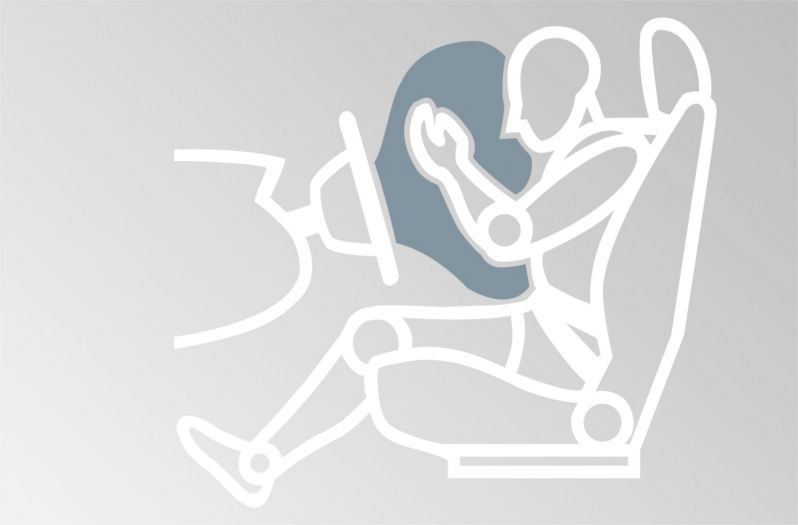
Thanks to the optimal coordination between the seat belt tensioner and airbag, the kinetic energy of the occupants is slowly dissipated over the course of the impact, which reduces the loads.

Battery switch-off

To avoid the danger of short circuits and resulting vehicle fires, the battery is disconnected from the vehicle electrical system in the event of an accident.


This is done using a cut-off relay or a gas generator. The battery disconnection signal is sent by the airbag control unit. The gas generator works in a similar way to the seat belt tensioner here. If the battery disconnection function is triggered, the connection between the battery and connecting cable is disconnected inside the terminal.

TESTING AND DIAGNOSTICS ON AIRBAG SYSTEMS: TROUBLESHOOTING

As a basic principle, work on the airbag system must only be performed by specialist, appropriately trained professionals.


All legal and manufacturer-specific regulations must be followed. The same applies to the disposal of any deployed or old airbags. It is advisable to train all workshop employees if possible, because many tasks which are not necessarily related directly to the airbag still require the airbag or seat belt tensioner to be removed. One example of this would be work on the instrument cluster.


As is the case for diagnostics and troubleshooting in other systems, the first step is to conduct a visual inspection. In the process, check all visible components of the airbag system for damage and to ensure the plug contacts are correctly connected. One common fault cause is a poor plug connection to the seat belt tensioners or side airbags in the area of the front seats. As the seats are moved forward and back the plug connections become loose, which causes contact resistance. The volute spring can also be a cause of faults. The spring can fail because it is placed under load each time the steering wheel is turned. A suitable diagnostic unit is always required. If the visual inspection reveals a faulty plug connection, clear the fault memory using the diagnostic unit.

If the visual inspection does not reveal any defects, read out the fault memory using the diagnostic unit. Faults which have occurred in the system are generally identified by the self-diagnostics and stored in the fault memory. If the fault "Signal faulty", "Signal too low", or "Signal too high" is stored in the fault memory, one possible cause may be a faulty cable, for example. In this case, a multimeter can be used to check the cable connections between the sensors and control unit for continuity and a short circuit to frame. Manufacturer-specific information and circuit diagrams are required to identify the sensors and plug connections and the pin assignment on the control unit. In the process, always ensure that the vehicle battery is disconnected and the sensors and control unit are disconnected from the wiring harness. Do not use any "home-made" test adapters (paper clips which have been bent open) to connect the test lines to the connectors. They could damage the sensitive plug contacts and may cause new faults which go unnoticed. It makes more sense to use special probes which fit into the plug contacts and ensure that correct contact is established.

How helpful is this article for you?

Not helpful at all

Very helpful

Please tell us what you did not like.
Many thanks. But before you go.

Sign up for our free HELLA TECH WORLD newsletter to receive the latest technical videos, car repair advice, training course information, marketing campaign details and diagnostic tips.

Show additional information on our newsletter Hide additional information on our newsletter

Register for our free HELLA TECH WORLD newsletter to stay up-to-date with the latest technical videos, car repair advice, trainings, diagnostic tips and marketing campaigns.

Together we can get cars back on the road quickly!

Please note:
You will only be subscribed to the newsletter once you have clicked on the confirmation link in the notification e-mail you will receive shortly!

Data Protection | Unsubscribe

Please note:
You will only be subscribed to the newsletter once you have clicked on the confirmation link in the notification e-mail you will receive shortly!

Data Protection | Unsubscribe

Almost there!

All you need to do is confirm your sign up!
We've sent an e-mail to your email address.

Check your inbox and click on the confirmation link to start receiving HELLA TECH WORLD updates.

Wrong e-mail or no confirmation received?
Click here to enter it again.