Idle speed regulator / idle speed control: Function, fault symptoms and troubleshooting

The idle speed controller ensures that the idle speed of the engine remains constant in all load conditions. On this page you can find out about how the idle speed actuator regulates the intake air mass of the engine, and how the failure of this actuator impacts on the engine running. Practical tips for troubleshooting and assembly instructions help to quickly rectify defects relating to the idle speed controller.

Important safety note

The following technical information and practical tips have been compiled by HELLA in order to provide professional support to vehicle workshops in their day-to-day work. The information provided on this website is intended for suitably qualified personnel only.

1. Functional principle

Idle speed controller function

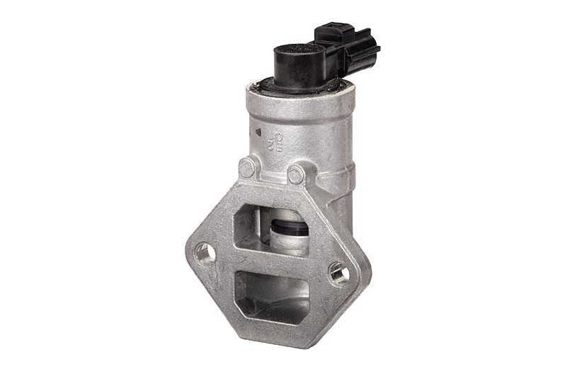
The idle speed actuator is a bypass air valve. The idle speed actuator shown as an example consists of a closed cast housing with flange-mounted solenoid valve servo unit. Attached to this is a nozzle holder, which releases different air cross sections by moving the servo unit, and can therefore control the air mass flow when the throttle valve is closed.

The idle speed actuator is responsible for regulating the engine speed as part of the overall idle-speed control of the engine management system. If there is a sudden change to the engine load condition when in idle mode (e.g. air-conditioning system being switched on, creep speed in 1st gear, or activation of another electrical consumer), air and fuel are also required in order to prevent the engine from stopping. If the engine speed falls below a certain critical value, which is stored as a constant in the control unit memory, the solenoid valve is activated and an increased air flow rate is achieved. The opening time of the injection valves is simultaneously extended and adapted to the engine's requirements.

2. Symptoms

Symptoms of a faulty idle speed controller

A faulty idle speed actuator can manifest itself as follows:

  • Fluctuating idle speed
  • Engine stops running at idle speed
  • Engine stops running at idle speed and activation of additional consumers
  • Engine indicator lamp comes on
3. Cause of failure

Causes for faulty idle speed controllers

Causes for failure of the idle speed actuator can be:

  • Contamination / resin formation
  • Short circuits in the coil
  • Electric magnetic drive becomes stuck
  • No voltage supply from the engine management control unit
4. Troubleshooting

Checking the idle speed actuator

The following test steps should be considered during troubleshooting:

1

Checking the voltage supply

Check the voltage supply with the ignition switched on.

  • Measured value: 11 – 14 V.

Note:
An Ohm measurement must only be carried out in a de-energized state (plug connection removed).

2

Measuring the coil resistance

Use the multimeter to measure the coil resistance between the two connection pins of the idle speed actuator.

  • Reference value = approx. 10 ohms (observe manufacturer's specifications).

3

Checking the coil for winding short circuit

Check the coil for a winding short circuit between the two connection pins.

  • Measured value in the event of a short circuit = 0 ohms.

4

Checking the coil for winding interruption

Check the coil for a winding interruption between the two connection pins.

  • Measured value in the event of an interruption = >30 MOhm.

5

Checking the coil for short circuit to frame

Check the coil for short circuit to frame – between pin 1 and component housing, and between pin 2 and component housing.

  • Measured value in the event of an unimpaired coil = >30 MOhm.

6

Mechanical check

Unscrew the servo unit from the housing. Visual check to determine whether the bypass opens and closes when the valve rod is actuated.

7

Read out fault code

Read out fault code.

ASSEMBLY INSTRUCTIONS

Before mounting the idle speed actuator, the supporting surface must be cleaned and, if necessary, the flange seal must be replaced.

Observe the tightening torque!

  • Fixing screws 12 – 15 Nm

Please observe the specifications provided by the respective vehicle manufacturer.

Mennyire hasznosnak találod ezt a cikket?

Egyáltalán nem segít
5
4
3
2
1
Nagyon hasznos
Siker

Helytelen Captcha

Helytelen Captcha

Hiba

Something went wrong

Pótalkatrész-kereső
Jármű kézi azonosítása OE-szám
A legjelentősebb gyártók
Egyéb gyártók
Járműsorozatok Vissza
Jármű Vissza

Írja be az OE-számot a beviteli mezőbe. Az OE-számot általában magán a pótalkatrészen vagy a jármű dokumentumaiban találja meg.

Pótalkatrész-kereső
Egyszerű járműazonosítás a KBA-szám alapján Határozza meg az eredeti alkatrészszámmal rendelkező pótalkatrészeket is Részletes termékinformációk Keressen nagykereskedőket a közelében
dummy
Processing Selected Car
Gyártó
Járműsorozatok
Jármű
Motor teljesítménye
Motor hengerűrtartalma
Üzemanyag-típus
Építés éve
Motor kódja

Válasszon kategóriát:
Vissza
dummy
Megosztás
Küldés a következőn keresztül Link másolása
Az URL-cím átmásolva a clickboardra!
Cikkszám
Number
A cikkszám lemásolták!
Keresés az interneten Szerelési útmutató
További részletek
Neve Érték
Kevesebb részlet

A kereskedője
Autoteile Krammer GmbH
dummy
Lechstraße 1-3
68199 Mannheim
Termékprospektus letöltése

Egy gyors kérdés

Great! Just one more Step

Subscription successful

Head to your inbox and confirm your email address so that you don’t miss our updates!

Get ready for brand new technical videos, car repair advice, trainings, helpful diagnostic tips, marketing campaigns and much more... delivered straight to your inbox every two weeks!