Check the multifunction controller on the generator and replace it safely.

Important safety note

The following technical information and practical tips have been compiled by HELLA in order to provide professional support to vehicle workshops in their day-to-day work. The information provided on this website is intended for use by suitably qualified personnel only.

1. Basics

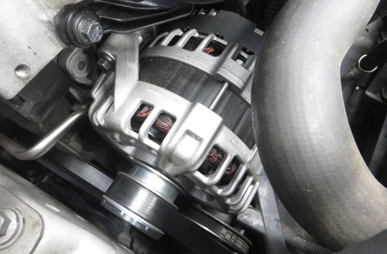
Alternator with multi-function regulator (MFR)

The ever increasing demand for electrical power requires particularly efficient and powerful alternators and regulators. These should have the option of consumer and battery management. For this reason, hybrid regulators are increasingly being replaced by monolithic regulators with new functions: these are called multi-function regulators

2. Function

Functions of a multi-function regulator

Multi-function regulators offer the following additional functions:

  • Battery monitoring (sensing)
  • Utilisation monitoring
  • Fault diagnostics
  • Engine management support
  • Load response

A multi-function regulator's functions in detail

In battery monitoring, the charging voltage of the battery is monitored via "S” connection, which is usually connected directly to the positive battery pole. The direct connection to the battery has the advantage that the existing voltage difference between alternator "+" and battery "+" is taken into account. This means that the charging voltage can be adapted even better to the battery voltage.

With the load control, it is possible to control the power of the alternator during the starting process and when the engine is running. This means that, during the starting process and directly after the engine start, the alternator does not output any current. This prevents the starting process from being prolonged by the full power (braking torque) of the alternator. If there are increased demands during the journey, leading to an increase in torque at the alternator, these are not passed on directly to the engine. The load response slowly increases the power output of the alternator.

The multi-function regulator also controls the pre-excitation current. After switching on the ignition, the regulator output stage starts to cycle in the set clock ratio. The alternator receives information that the ignition is switched on via connection terminal "L". The alternator control lamp remains on while the pre-excitation is active. The evaluation of the phase voltage identifies that the alternator is rotating. If pre-excitation is missing, e.g. due to a faulty plug contact, the emergency mode ensures excitation of the alternator. The idle current cut-off reduces the current consumption of the regulator as much as possible when the ignition is switched off.

If the battery monitoring line to battery "+" is disconnected, an "emergency regulation" takes place via the "B+" connection on the alternator. To protect the regulator against overheating, the temperature is measured on the IC. If the temperature rises too high, the controller voltage is reduced

Multi-function regulator connections

“L” = The “L” connection has several functions. The "L" connection is used to display the alternator function and any faults that have occurred. The control lamp is actuated via the lamp output stage. Consumers can also be connected via a relay output stage. The consumers should only be switched on when the alternator has reached its full output in fault-free operation. For this, the "L” connection provides an output current via the relay output stage. To detect faults, all signals are constantly evaluated by the regulator and any faults that occur are detected. A fault is indicated by the control lamp turning on via the lamp output stage. The lamp and relay output stages are protected against overload and short circuits. Here, the lamp output stage is active during alternator pre-excitation or when a fault is detected. The relay output stage for connecting the consumers is active during fault-free alternator operation when the lamp output stage is inactive.

"S" = The "S" connection is connected directly to battery "+" to measure the battery voltage as an actual value.

"DFM" = The "DFM” connection (DF monitor) facilitates recording the alternator’s present utilisation status. This makes it possible to react to certain situations, such as raising the idle speed or switching off consumers that are not required. The signal curve of "DF" can be picked up at the "DFM" connection.

"W" At the "W" connection, it is possible to pick up the voltage signal of an alternator phase.
3. Cause of failure

General effects and causes of a multi-function regulator failure

A multi-function regulator failure can have the following effects:

  • The alternator control lamp lights up
  • Discharged battery

Causes of failure can be traced back to various causes:

  • Interrupted output stage
  • Overvoltage in the vehicle electrical system
  • Charging cable interrupted
  • Battery monitoring cable interrupted
  • Fault in/on the alternator (broken drive belt, short circuit in the excitation circuit, etc.)

These errors are detected by the multi-function regulator depending on the regulator type

4. Troubleshooting

Check multi-function regulator:

1

Visual inspection

  • Check all cable connections and plug contacts for correct routing and contacting.
    Check alternator drive belt for correct tension and any cracks

2

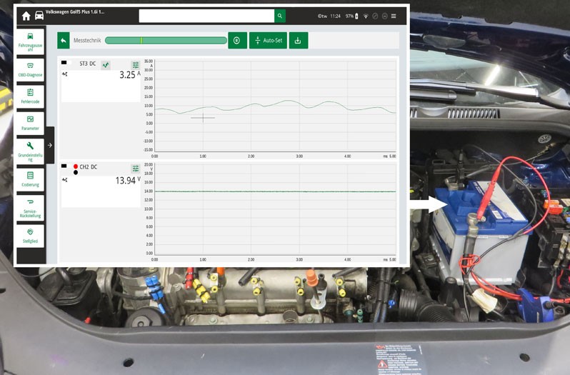
Measure the alternator voltage/alternator

Measure the alternator voltage/alternator current at the battery (observe manufacturer's specifications, differences between manufacturers). Carry out measurements at idle speed and increased engine speed, without and with consumers connected.

3

Checking the signal at controller connection „DFM“

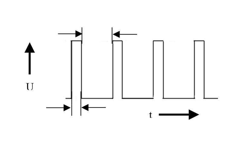
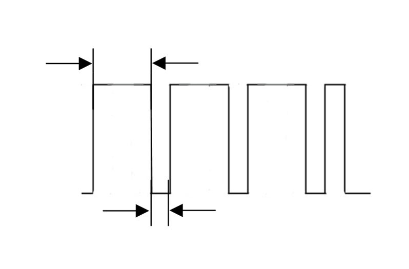
Record the signal at the DFM connection with the oscilloscope. The signal shown reflects the duty cycle of the excitation current. Depending on the load condition of the alternator, the duty cycle must change.

Link to tip

Here you will find tips and remedies for specific symptoms and causes for the failure of a defective alternator . In addition, we show you on this page how to check the charging system , such as carrying out a visual inspection before diagnosis, testing the batteries, performing the alternator test and testing with the diagnostic device. You can find more product information about starters and alternators from Hella here

Jak moc vám tento článek pomohl?

Vůbec nepomohl
5
4
3
2
1
Velmi užitečný
Děkujeme za váš názor!

Nesprávný kód Captcha

Nesprávný kód Captcha

Došlo k chybě

Something went wrong

Vyhledávač náhradních dílů
Číslo dílu Ruční identifikace vozidla Univerzální díly
Přední výrobce
Ostatní výrobci
Řada vozidel Zpět
Vozidlo Zpět

Zadejte číslo OE do vstupního pole. Číslo OE obvykle najdete přímo na náhradním dílu nebo v dokladech k vozidlu.

Vyhledávač náhradních dílů
Určete také náhradní díly podle čísel originálních dílů (OE) Podrobné informace o produktu Najděte velkoobchody ve vašem okolí
dummy
Processing Selected Car
Výrobce
Řada vozidel
Vozidlo
Výkon motoru
Objem motoru
Druh paliva
Rok výroby
Kód motoru

Vyberte kategorii:
Zpět
dummy
Sdílejte
Odeslat přes Kopírovat odkaz
URL byla zkopírována do schránky!
Číslo článku
Number
Číslo článku bylo zkopírováno!
Vyhledávání na webu Návod k montáži
Další podrobnosti
Jméno Hodnota
Zobrazit méně podrobností

Váš prodejce
Autoteile Krammer GmbH
dummy
Lechstraße 1-3
68199 Mannheim
Zobrazit mapu

You might also be interested in

TPS sensor
Základní znalosti
TPS sensor – function & troubleshooting
Learn how to check a throttle potentiometer for defects and recognize the most common symptoms.
Doba čtení: 2 minuty
Throttle valve switch
Základní znalosti
Throttle valve switch – function & troubleshooting
Everything you need to know to diagnose and repair the throttle valve switch - helpful workshop tips.
Doba čtení: 2 minuty
Camshaft position sensor
Základní znalosti
Camshaft position sensor - function & troubleshooting
Learn all about the function and testing of the camshaft sensor and possible symptoms of a defect.
Doba čtení: 2 minuty
Accelerator pedal sensor
Základní znalosti
Accelerator pedal sensor – function & design
Important tips for checking the accelerator pedal sensor and rectifying defects - practical knowledge for your workshop.
Doba čtení: 3 minuty
Injection nozzle/injection valve
Základní znalosti
Injection nozzle/injection valve – Function & checks
Find out how to diagnose a defective fuel injector and replace it in the workshop.
Doba čtení: 6 minut
Základní znalosti
Checking the exhaust gas temperature sensor
Step-by-step instructions for testing the exhaust gas temperature sensor - shown on the VW Passat 2.0 TDI.
Doba čtení: 3 minuty
Idle speed controllers / idle speed actuators
Základní znalosti
Idle speed controller & actuator - function & check
Everything you need to know about testing and troubleshooting idle speed regulators: function, typical symptoms and repair tips for your workshop.
Doba čtení: 3 minuty
Intake-air temperature sensor
Základní znalosti
Intake-air temperature sensor - checking & faults
Discover how to check the intake air temperature sensor for defects and how to replace it efficiently.
Doba čtení: 3 minuty
What is a lambda sensor?: Comprehensive technical information
Základní znalosti
Lambda sensor testing and troubleshooting
Find out how to check and measure lambda sensors - with step-by-step instructions for fault diagnosis.
Doba čtení: 14 minut
Air-mass sensor
Základní znalosti
Air-mass sensor - Function & troubleshooting
Learn how to check a mass air flow sensor, detect defective sensors and replace them professionally.
Doba čtení: 2 minuty