
Understanding the secondary air system and diagnosing faults in a targeted manner

The secondary air system reduces harmful exhaust constituents during the cold start phase. On this page, you can find out precisely how this works. Here you can also read how malfunctions in the secondary air system become noticeable and how they can be precisely located during troubleshooting.

Important safety note

The following technical information and practical tips have been compiled by HELLA in order to provide professional support to vehicle workshops in their day-to-day work. The information provided on this website is intended for suitably qualified personnel only.

1. Basics

Why is a secondary air system used?

This system further lowers the HC and CO values during the cold start phase when the catalytic converter is not yet active.

A conversion rate of over 90 percent is achieved using a 3-way catalytic converter in stoichiometrically operated gasoline engines. On average, up to 80 percent of the emissions of a driving cycle are emitted during a cold start. However, because the catalytic converter only works effectively from temperatures of approx. 300°C – 350°C, the emissions must be lowered during the cold start phase using different measures. This is the task of the secondary air system.

If there is sufficient residual oxygen in the exhaust system and the temperature is high enough, the HC and CO react in a secondary reaction to form CO2 and H2O.

To ensure there is enough oxygen for the reaction during the cold start phase, when the mixture is very rich, air is added to the exhaust flow. For vehicles with a three-way catalytic converter and a lambda control , the secondary air system is switched off after approx. 100 seconds. The operating temperature of the catalytic converter is quickly reached through the heat generated in the secondary reaction.

The secondary air can be supplied actively or passively. In the passive system, fluctuations in pressure in the exhaust system are utilised. Additional air is drawn in via a timed valve due to the vacuum created through the flow speed in the exhaust pipe. In an active system, the secondary air is blown in by a pump. This system allows better control.

2. Structure

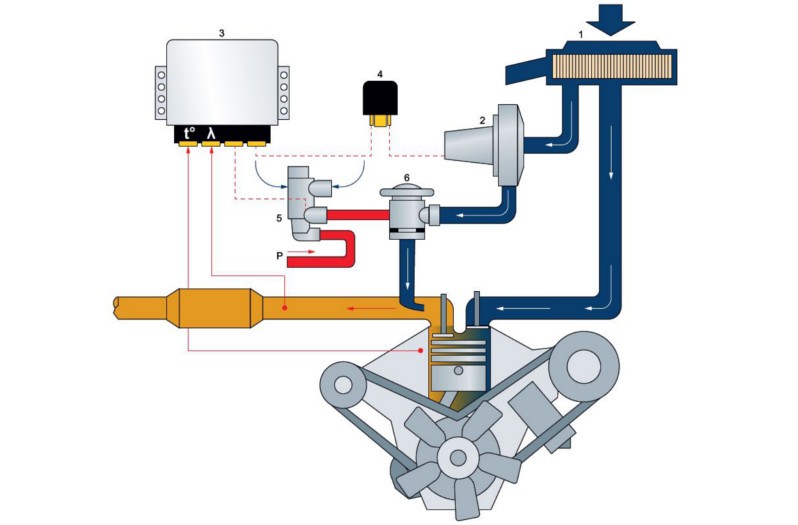
Structure of the active secondary air system

1 Air filter
2 Secondary air pump
3 Engine control unit
4 Control relay
5 Change-over valve
6 Combination valve
---------- currentless

3. Function

Function of the active secondary air system

The active secondary air system usually consists of an electric pump (see figure), the control relay, a pneumatic control valve, and a combination valve. The system is controlled by the engine control unit.

While the system is working, the electric pump is switched on by the engine control unit via the control relay. The pneumatic control valve is actuated at the same time. The valve opens and the vacuum from the intake pipe operates the combination valve.

The vacuum causes the combination valve to open and the additional air conveyed by the pump is pumped into the exhaust pipe behind the exhaust valves. As soon as the lambda control becomes active, the secondary air system is deactivated. The engine control unit deactivates the electric pump and the pneumatic control valve. The combination valve is also closed, preventing hot exhaust emissions from reaching the electric pump and damaging it.

4. Symptoms

Fault symptoms in the event of failure

Increased emission values during the cold start and warm-up phases can be caused by a lack of post-combustion. The catalytic converter only reaches its operating temperature at a later point. Secondary air systems which are monitored by the engine control unit's self-diagnosis function, cause the engine indicator lamp to illuminate in the event of faults.

5. Cause of failure

Causes of a failure

A faulty pump is generally the most frequent cause of the system failing. Ingress of moisture can cause damage which results in seizure of the pump. Faulty ground and voltage supply can also cause the pump to fail. Blocked or leaking lines can also cause the failure or malfunction of the control or combination valve, resulting in the failure of the secondary air system.

6. Troubleshooting

Troubleshooting and diagnostics on secondary air systems

As for all other troubleshooting and diagnostic work, begin with visual checks, and additionally an acoustic check. For the acoustic check, the electric pump is audible when the engine is cold and at idle. The sound of the pump stopping can also clearly be heard after the engine has been turned off. For the visual check, all components should be checked for damage. The cables and hose fittings should be checked particularly closely. These parts should be correctly attached to the components and not show any signs of chafing. They must also not be kinked or blocked due to excessively tight radii. The fuses must also be present and checked for damage. If during these tests no fault can be determined, a suitable diagnostic unit can be used for further diagnostics. The basic prerequisite is that the system has been provided with diagnostic capabilities by the vehicle manufacturer.

1

Reading stored faults

Any stored faults can be read out from the fault memory and rectified.

If no faults are stored in the fault memory, the electric pump can be switched on using the actuator test. During this test, the function of the control relay is also tested at the same time.

The triggering of the control valve can also be checked with the actuator test. The function of the control valve can also be tested without a diagnostic unit. For this, remove the vacuum line which leads to the combination valve. Start the cold engine.

2

Checking the vacuum at the control valve fitting

At the control valve fitting, it should be possible to detect a vacuum (a vacuum pump can also be connected) as soon as the secondary air pump begins to operate

3

Checking the triggering of the control valve

If no vacuum can be detected, check the triggering of the control valve using a multimeter. If this is OK, a faulty control valve can be presumed to be the cause.

4

Checking the function of the combination valve

The function of the combination valve can be checked using a vacuum pump. For this, remove the vacuum line at the combination valve and connect the vacuum pump to the valve.

5

Checking the hose fitting

Now loosen the hose fitting from the secondary air pump to the combination valve at the pump.

Blow air into the line with a slight pressure (do not use compressed air). The combination valve must be closed.

Apply a vacuum to the combination valve and blow air into the hose fitting again. The combination valve must now be opened. If the combination valve does not open, or if it is permanently open, the valve is faulty.

Note

During all diagnostic and testing procedures, information from the vehicle manufacturer should always be adhered to if possible. From manufacturer to manufacturer, there may be vehicle-specific information and testing methods which may have to be taken into consideration.

Jak moc vám tento článek pomohl?

Vůbec nepomohl
5
4
3
2
1
Velmi užitečný
Děkujeme za váš názor!

Nesprávný kód Captcha

Nesprávný kód Captcha

Došlo k chybě

Something went wrong

Vyhledávač náhradních dílů
Číslo dílu Ruční identifikace vozidla Univerzální díly
Přední výrobce
Ostatní výrobci
Řada vozidel Zpět
Vozidlo Zpět

Zadejte číslo OE do vstupního pole. Číslo OE obvykle najdete přímo na náhradním dílu nebo v dokladech k vozidlu.

Vyhledávač náhradních dílů
Určete také náhradní díly podle čísel originálních dílů (OE) Podrobné informace o produktu Najděte velkoobchody ve vašem okolí
dummy
Processing Selected Car
Výrobce
Řada vozidel
Vozidlo
Výkon motoru
Objem motoru
Druh paliva
Rok výroby
Kód motoru

Vyberte kategorii:
Zpět
dummy
Sdílejte
Odeslat přes Kopírovat odkaz
URL byla zkopírována do schránky!
Číslo článku
Number
Číslo článku bylo zkopírováno!
Vyhledávání na webu Návod k montáži
Další podrobnosti
Jméno Hodnota
Zobrazit méně podrobností

Váš prodejce
Autoteile Krammer GmbH
dummy
Lechstraße 1-3
68199 Mannheim
Zobrazit mapu

You might also be interested in

TPS sensor
Základní znalosti
TPS sensor – function & troubleshooting
Learn how to check a throttle potentiometer for defects and recognize the most common symptoms.
Doba čtení: 2 minuty
Throttle valve switch
Základní znalosti
Throttle valve switch – function & troubleshooting
Everything you need to know to diagnose and repair the throttle valve switch - helpful workshop tips.
Doba čtení: 2 minuty
Camshaft position sensor
Základní znalosti
Camshaft position sensor - function & troubleshooting
Learn all about the function and testing of the camshaft sensor and possible symptoms of a defect.
Doba čtení: 2 minuty
Accelerator pedal sensor
Základní znalosti
Accelerator pedal sensor – function & design
Important tips for checking the accelerator pedal sensor and rectifying defects - practical knowledge for your workshop.
Doba čtení: 3 minuty
Injection nozzle/injection valve
Základní znalosti
Injection nozzle/injection valve – Function & checks
Find out how to diagnose a defective fuel injector and replace it in the workshop.
Doba čtení: 6 minut
Základní znalosti
Checking the exhaust gas temperature sensor
Step-by-step instructions for testing the exhaust gas temperature sensor - shown on the VW Passat 2.0 TDI.
Doba čtení: 3 minuty
Idle speed controllers / idle speed actuators
Základní znalosti
Idle speed controller & actuator - function & check
Everything you need to know about testing and troubleshooting idle speed regulators: function, typical symptoms and repair tips for your workshop.
Doba čtení: 3 minuty
Intake-air temperature sensor
Základní znalosti
Intake-air temperature sensor - checking & faults
Discover how to check the intake air temperature sensor for defects and how to replace it efficiently.
Doba čtení: 3 minuty
What is a lambda sensor?: Comprehensive technical information
Základní znalosti
Lambda sensor testing and troubleshooting
Find out how to check and measure lambda sensors - with step-by-step instructions for fault diagnosis.
Doba čtení: 14 minut
Air-mass sensor
Základní znalosti
Air-mass sensor - Function & troubleshooting
Learn how to check a mass air flow sensor, detect defective sensors and replace them professionally.
Doba čtení: 2 minuty