ABS and ESP control units: Function, diagnosis and repair instructions

Important safety note

The following technical information and practical tips have been compiled by HELLA in order to provide professional support to vehicle workshops in their day-to-day work. The information provided on this website is intended for suitably qualified personnel only.

1. Basics

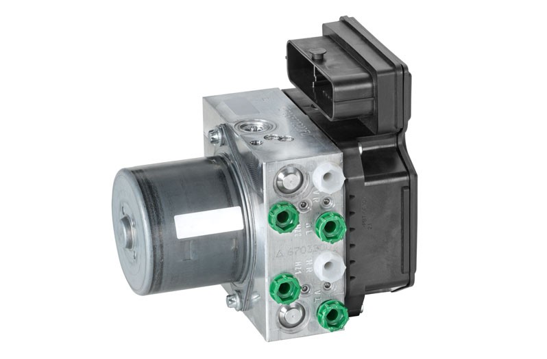
Brake system hydraulic unit with control unit for braking and driving dynamics

The hydraulic unit of the brake system with its control unit for braking and driving dynamics has become part of standard equipment in many vehicle models.

The Electronic Stability Programme (ESP) has the task of preventing lateral swerving when cornering or when faced with critical situations, e.g. during extreme driving manoeuvres. The system specifically intervenes in the braking system and in the engine and transmission management and keeps the vehicle on track. It is important that during such intervention physical laws cannot be overridden. As soon as the limits are exceeded, even the ESP system cannot prevent the vehicle from swerving.

As the number of vehicles equipped with ABS/ASR or ESP increases, not surprisingly the frequency of faults and the need for repairs in the workshop also increase.

Hydraulic unit of the brake system

The hydraulic unit contains the shift valves for the individual wheel brakes, which are necessary for the controlling of brake pressure. They are used in the hydraulic unit to control the 3 pressure states that require regulation: i.e. building up pressure, maintaining pressure, reducing pressure.
The hydraulic pump is used to generate the necessary admission pressure on the intake side of the return pump of the ABS system . The return pump is not able to build up the necessary initial pressure if the brake pedal is not depressed and there is no pressure present in the system.

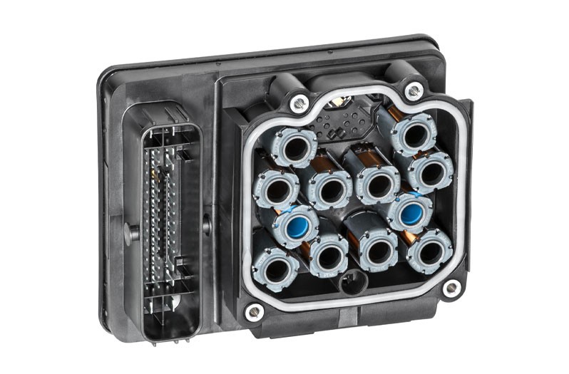
Control unit for braking and driving dynamics

The control unit for braking and driving dynamics is usually fitted to the hydraulic unit.

The control unit consists of a powerful computer. So as to ensure the highest possible safety levels, the system consists of two computers with their own power supply and diagnostic interface, which use the same software. All information is processed in parallel and the computers monitor each other. The control unit is also responsible for controlling the ABS/ASR and the ESP. All systems are combined in one control unit.

2. Troubleshooting

Failure of ABS/ESP system

If the ABS/ESP system fails, this will be indicated by the control lamp lighting up permanently. A visual inspection should always be carried out in every case before complex and time-consuming diagnostics work is undertaken. During such inspection, particular attention should be paid to checking whether any leaks are present or whether components are damaged. If no abnormalities are detected during the visual inspection, a diagnostic unit is then used for further testing.

The ABS/ESP system has a self-diagnostic feature. This means it detects errors such as line interruptions, short circuits to earth(ground) or positive and also defects in the sensors. These errors can be stored in the error memory of the control unit and read. A diagnosis can be carried out on the ABS/ESP system with an appropriate diagnostic unit. Depending on the unit used, there is a wide range of testing possibilities available, checks which go as far as including a specially prescribed system test.

1

Reading the error memory

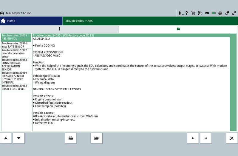
The first step is the reading out of the error memory. Any errors that occur are stored here and provide initial indications of the possible cause of the error. The stored error can give a direct indication about a defective component (Figure - Error memory 2) or about a short circuit/cable interruption. This allows targeted repair work to be carried out.
2

Reading parameters

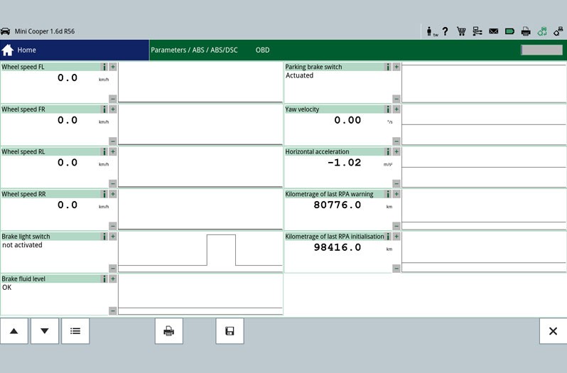
If no errors are stored in the error memory, parameters can be read out and evaluated specifically with the aid of an actual value query. Technical documents with the required set points are necessary for the evaluating of the displayed actual values, unless these are stored in the diagnostic unit. Errors which are stored in the error memory are also displayed during the actual value query.

3

Actuator test

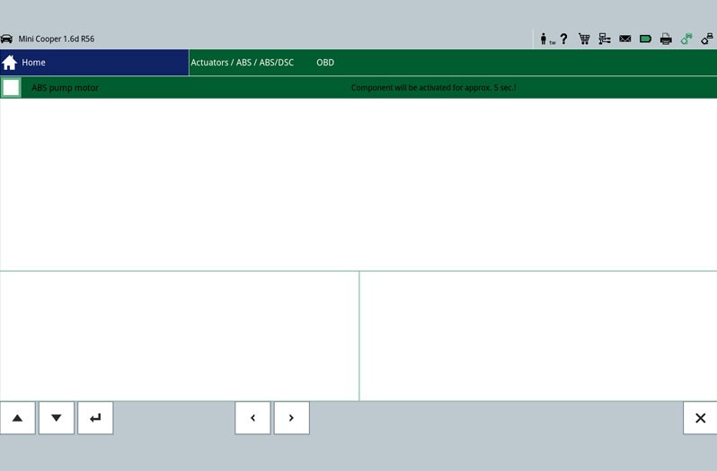
Another test option is the actuator test. During this test, individual components can be controlled by the diagnostic unit and thus their functioning checked.

4

Basic setting

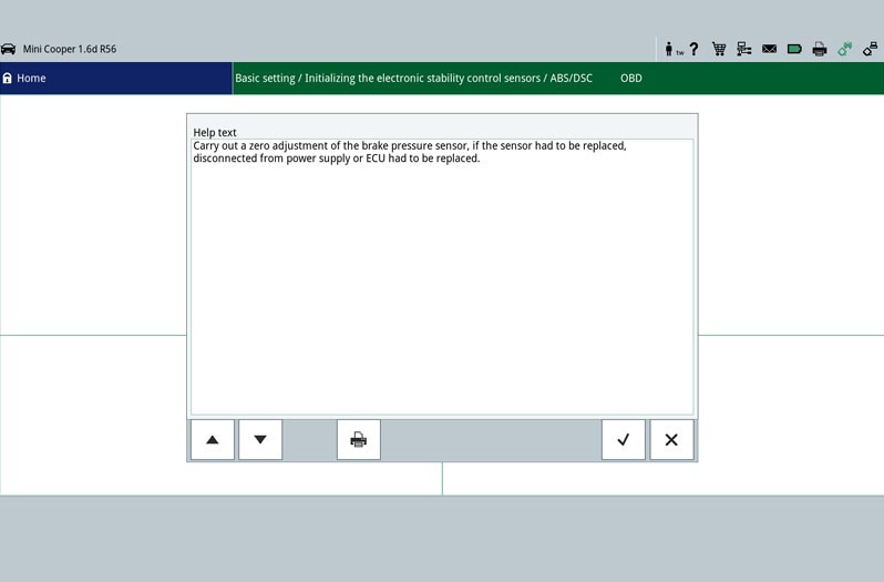
In this function, components, such as the sensors of the vehicle dynamics control system, can be set or adapted according to manufacturer values. The prerequisite for a basic setting is a vehicle system in perfect working order.

5

Identification

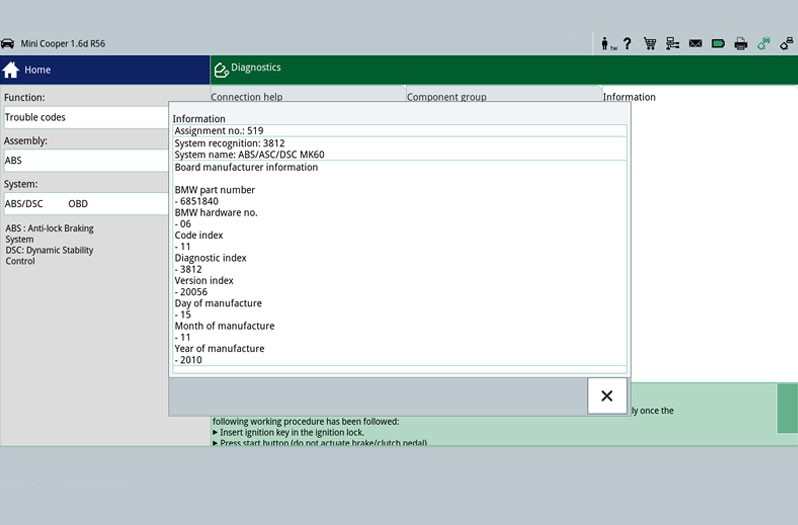
Special system and control unit information can be called up here.

6

Circuit diagrams

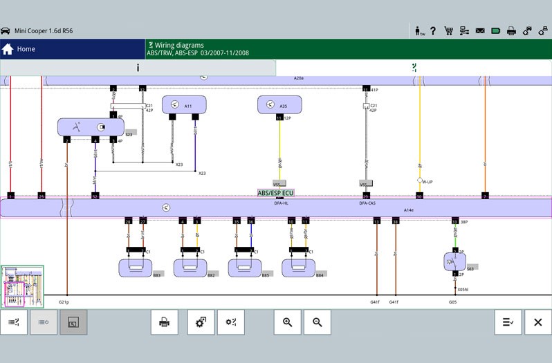
System-specific circuit diagrams can be taken from vehicle information and used for troubleshooting purposes. This is where the PIN assignment on the control unit plug or the cable colours can be read and used for further testing on the electric vacuum pump or on the brake booster pressure sensor.

Important

The various diagnostic possibilities were illustrated using the mega macs 77 diagnostic unit on a MINI ONE 1.6 R56 as an example. The relevant depth of inspection and the variety of functions depend on each individual system configuration of the control unit.

3. Effects

Fault in the electrical system

If a fault is detected in the electrical system, the following measures are initiated:

  • The ABS/ESP system is switched off. The brake system continues to work in the usual way.
  • The fault is shown by the ABS/ESP indicator/control light
4. Important information

Important repair instructions

The following repair instructions are to be strictly observed!

  • Because of its intervention in the brake system, the braking and driving dynamics control unit or the brake system hydraulic unit may only be replaced by trained personnel.
  • After installation of the ABS control unit, it is necessary to adapt it to the vehicle! Please use a suitable diagnostic unit for this purpose.
  • For all repair work on the brake system, please observe the safety and installation instructions provided by the system or vehicle manufacturer in question.
  • If necessary, please use the installation or removal tools specified by the vehicle manufacturer.
  • Repair work that is carried out incorrectly can lead to system failure and to severe personal injuries
  • A
  • B
  • C
  • D
  • E
  • F
  • G
  • H
  • I
  • J
  • K
  • L
  • M
  • N
  • O
  • P
  • Q
  • R
  • S
  • T
  • U
  • V
  • W
  • X
  • Y
  • Z

Anti-lock braking system (ABS)

Prevents the wheels from locking during braking. The steerability and lane stability of the vehicle are maintained.

Electronic stability programme (ESP)

Prevents the vehicle from swerving or skidding by targeted intervention in the brake system and the engine control.

Traction control system (ASR)

Prevents the drive wheels from spinning, on snow or ice, by intervening in the brake system and the engine control.

Jak moc vám tento článek pomohl?

Vůbec nepomohl
5
4
3
2
1
Velmi užitečný
Děkujeme za váš názor!

Nesprávný kód Captcha

Nesprávný kód Captcha

Došlo k chybě

Something went wrong

Vyhledávač náhradních dílů
Číslo dílu Ruční identifikace vozidla Univerzální díly
Přední výrobce
Ostatní výrobci
Řada vozidel Zpět
Vozidlo Zpět

Zadejte číslo OE do vstupního pole. Číslo OE obvykle najdete přímo na náhradním dílu nebo v dokladech k vozidlu.

Vyhledávač náhradních dílů
Určete také náhradní díly podle čísel originálních dílů (OE) Podrobné informace o produktu Najděte velkoobchody ve vašem okolí
dummy
Processing Selected Car
Výrobce
Řada vozidel
Vozidlo
Výkon motoru
Objem motoru
Druh paliva
Rok výroby
Kód motoru

Vyberte kategorii:
Zpět
dummy
Sdílejte
Odeslat přes Kopírovat odkaz
URL byla zkopírována do schránky!
Číslo článku
Number
Číslo článku bylo zkopírováno!
Vyhledávání na webu Návod k montáži
Další podrobnosti
Jméno Hodnota
Zobrazit méně podrobností

Váš prodejce
Autoteile Krammer GmbH
dummy
Lechstraße 1-3
68199 Mannheim
Zobrazit mapu

You might also be interested in

Tire pressure monitoring system tpms
Základní znalosti
TPMS – tyre pressure monitoring system
Overview of direct and indirect tire pressure monitoring systems (TPMS) - everything you need to know for the vehicle workshop.
Doba čtení: 15 minut
TPS sensor
Základní znalosti
TPS sensor – function & troubleshooting
Learn how to check a throttle potentiometer for defects and recognize the most common symptoms.
Doba čtení: 2 minuty
Throttle valve switch
Základní znalosti
Throttle valve switch – function & troubleshooting
Everything you need to know to diagnose and repair the throttle valve switch - helpful workshop tips.
Doba čtení: 2 minuty
Camshaft position sensor
Základní znalosti
Camshaft position sensor - function & troubleshooting
Learn all about the function and testing of the camshaft sensor and possible symptoms of a defect.
Doba čtení: 2 minuty
Accelerator pedal sensor
Základní znalosti
Accelerator pedal sensor – function & design
Important tips for checking the accelerator pedal sensor and rectifying defects - practical knowledge for your workshop.
Doba čtení: 3 minuty
Injection nozzle/injection valve
Základní znalosti
Injection nozzle/injection valve – Function & checks
Find out how to diagnose a defective fuel injector and replace it in the workshop.
Doba čtení: 6 minut
Základní znalosti
Checking the exhaust gas temperature sensor
Step-by-step instructions for testing the exhaust gas temperature sensor - shown on the VW Passat 2.0 TDI.
Doba čtení: 3 minuty
Idle speed controllers / idle speed actuators
Základní znalosti
Idle speed controller & actuator - function & check
Everything you need to know about testing and troubleshooting idle speed regulators: function, typical symptoms and repair tips for your workshop.
Doba čtení: 3 minuty
Intake-air temperature sensor
Základní znalosti
Intake-air temperature sensor - checking & faults
Discover how to check the intake air temperature sensor for defects and how to replace it efficiently.
Doba čtení: 3 minuty
What is a lambda sensor?: Comprehensive technical information
Základní znalosti
Lambda sensor testing and troubleshooting
Find out how to check and measure lambda sensors - with step-by-step instructions for fault diagnosis.
Doba čtení: 14 minut